Autotiler
The Autotiler is a c library runs on users PCs before GAP code compilation and automatically generates GAP code for memory tiling and transfers between all memory levels: GAP has two levels in-chip memory (L1 and L2) and an external optional 3rd level (L3). The code generated makes use of micro-DMA (uDMA) which transfers data from external memories (Flash and L3) to internal L2 memory and of cluster-DMA (DMA) which tranfer data from L2 to L1. The Autotiler is part of the GapFlow to convert ONNX and TFlite Models onto GAP code.
From a user perspective, the purpose of the auto-tiler is twofold:
Use the Generators provided in the GAP SDK that contains several ready to go, optimized algorithms, like CNN/RNN layers, sound and image processing.
Create new generators with your own algorithms.
For several use cases the former will be enough to build your own application. The simplest way to use the Autotiler is to exploit the exhisting generators and just write your own model (or generate the model with NNtool).
Use generators provided within the SDK
To exploit generators provided in the sdk, the user needs to write his own model.
In the SDK we provide several examples on how to write your own model:
cd $GAP_SDK_HOME/examples/gap9/nn/autotiler/
All the generators source code can be found here:
cd $GAP_SDK_HOME/tools/autotiler_v3/
You can browse it here on Github.
Autotiler Models
An Autotiler model is a list of calls to generators that compose the processing that you want to perform on the cluster. A model is composed of 3 main parts:
Control code
Generators calls. Each Generator call can be seen as the node generation of graph.
Graph creation (optional). The graph creation permits to interconnect all the nodes generated by the Generators call and set input and output of the graph.
Here is a simple example of a MNIST NN Autotiler Model that can be found in $GAP_SDK_HOME/examples/gap9/nn/autotiler/
#include <stdint.h>
#include <stdio.h>
#include "AutoTilerLib.h"
#include "CNN_Generators.h"

void MnistModel(unsigned int L1Memory, unsigned int L2Memory, unsigned int L3Memory, unsigned int L3Flash)
{

    KernelOper_T Cop = KOP_CONV_DP;

    SetSymbolDynamics();

    SetUsedFilesNames(0, 2, "CNN_BasicKernels.h", "MnistKernels.h");
    SetGeneratedFilesNames("MnistKernels.c", "MnistKernels.h");
    SetMemoryDeviceInfos(4,
        AT_MEM_L1, L1Memory, "Mnist_L1_Memory", 0, 0,
        AT_MEM_L2, L2Memory, "Mnist_L2_Memory", 0, 0,
        AT_MEM_L3_DEFAULTRAM, L3Memory, "Mnist_L3_Memory", 0, 0,
        AT_MEM_L3_DEFAULTFLASH, L3Flash, "0", "Mnist_L3_Flash_Const.dat", 0
    );

    AT_SetGraphCtrl(AT_GRAPH_TRACE_EXEC, AT_OPT_ON);

    LoadCNNLibrary();
    //Convolutional Layer
    CNN_ConvolutionPoolReLU("Conv5x5ReLUMaxPool2x2_0", 0, 2,2,2,2, 12,14,14,12, 1,1,1,1, 1,32,28,28,
        Cop, 5, 5, 1, 1, 1, 1, 0,
        KOP_MAXPOOL, 2, 2, 1, 1, 2, 2, 0, KOP_RELU);
    //Convolutional Layer
    CNN_ConvolutionPoolReLU("Conv5x5ReLUMaxPool2x2_1", 0, 2,2,2,2, 12,14,14,12, 1,1,1,1, 32,64,12,12,
        Cop, 5, 5, 1, 1, 1, 1, 0,
        KOP_MAXPOOL, 2, 2, 1, 1, 2, 2, 0, KOP_RELU);
    //Linear Layer
    CNN_LinearReLU("LinearLayerReLU_0", 0, 2,2,2,2, 12,12,8,11, 2,2,2,2, 1024, 10,
        KOP_LINEAR, KOP_NONE);
    //Sofmax
    CNN_SoftMax("SoftMax_0", 0, 2,2, 15,15,1,1, 10, KOP_SOFTMAX);

#define GRAPH
#ifdef GRAPH
    //Open Graph Creation
    CreateGraph("MnistCNN",
        /* Arguments either passed or globals */
        //Here goes input, output and layers parameters(weights and biases)
        //ConstInfo function takes as input a tensor in CxHxW format and create a single binary file charged in  flash
        //It can take in input float and automaticcaly convert in fixed point format
        CArgs(8,
            TCArgInfo("short int *__restrict__", "Input0", ARG_SCOPE_ARG, ARG_DIR_IN, AT_MEM_L2, AT_MEM_UNDEF, 0),
            TCArgInfo("short int *__restrict__", "Step1Weights", ARG_SCOPE_GLOBAL, ARG_DIR_CONSTIN, AT_MEM_L3_HFLASH, AT_MEM_UNDEF, ConstInfo("model/Step1Weights.tensor", 1, 1, 16, 0)),
            TCArgInfo("short int *__restrict__", "Step1Biases",  ARG_SCOPE_GLOBAL, ARG_DIR_CONSTIN, AT_MEM_L3_HFLASH, AT_MEM_UNDEF, ConstInfo("model/Step1Biases.tensor"  , 1, 1, 16, 0)),
            TCArgInfo("short int *__restrict__", "Step2Weights", ARG_SCOPE_GLOBAL, ARG_DIR_CONSTIN, AT_MEM_L3_HFLASH, AT_MEM_UNDEF, ConstInfo("model/Step2Weights.tensor", 1, 1, 16, 0)),
            TCArgInfo("short int *__restrict__", "Step2Biases",  ARG_SCOPE_GLOBAL, ARG_DIR_CONSTIN, AT_MEM_L3_HFLASH, AT_MEM_UNDEF, ConstInfo("model/Step2Biases.tensor"  , 1, 1, 16, 0)),
            TCArgInfo("short int *__restrict__", "Step3Weights", ARG_SCOPE_GLOBAL, ARG_DIR_CONSTIN, AT_MEM_L3_HFLASH, AT_MEM_UNDEF, ConstInfo("model/Step3Weights.tensor", 1, 1, 16, 0)),
            TCArgInfo("short int *__restrict__", "Step3Biases",  ARG_SCOPE_GLOBAL, ARG_DIR_CONSTIN, AT_MEM_L3_HFLASH, AT_MEM_UNDEF, ConstInfo("model/Step3Biases.tensor"  , 1, 1, 16, 0)),
            TCArgInfo("short int *__restrict__", "Output0", ARG_SCOPE_ARG, ARG_DIR_OUT, AT_MEM_UNDEF, AT_MEM_L2, 0)
        ),
        //Graph internal buffer between layers
        /* Locals, allocated dynamically */
        CArgs(3,
            TCArgInfo("short int *__restrict__", "OutputStep2", ARG_SCOPE_LOCAL, ARG_DIR_INOUT, AT_MEM_UNDEF, AT_MEM_UNDEF, 0),
            TCArgInfo("short int *__restrict__", "OutputStep3", ARG_SCOPE_LOCAL, ARG_DIR_INOUT, AT_MEM_UNDEF, AT_MEM_UNDEF, 0),
            TCArgInfo("short int *__restrict__", "OutputStep4", ARG_SCOPE_LOCAL, ARG_DIR_INOUT, AT_MEM_UNDEF, AT_MEM_UNDEF, 0)
        )
    );
    //Node Connections with arguments
    AddNode("Conv5x5ReLUMaxPool2x2_0", //Name of the Generated Layer
            Bindings(4,                //Number of parameters that genereted layers has and that needs to be connected
                                                        //void Conv5x5ReLUMaxPool2x2_0(
                GNodeArg(GNA_IN, "Input0", 0),          //short int * __restrict__ In,
                GNodeArg(GNA_IN, "Step1Weights", 0),    //short int * __restrict__ Filter,
                GNodeArg(GNA_IN, "Step1Biases", 0),     //short int * __restrict__ Bias,
                GNodeArg(GNA_OUT, "OutputStep2", 0)    //short int * __restrict__ Out
                )
            );

    AddNode("Conv5x5ReLUMaxPool2x2_1", Bindings(4, GNodeArg(GNA_IN, "OutputStep2", 0), GNodeArg(GNA_IN, "Step2Weights", 0), GNodeArg(GNA_IN, "Step2Biases", 0), GNodeArg(GNA_OUT, "OutputStep3",0)));
    AddNode("LinearLayerReLU_0", Bindings(4, GNodeArg(GNA_IN, "OutputStep3", 0), GNodeArg(GNA_IN, "Step3Weights", 0), GNodeArg(GNA_IN, "Step3Biases", 0), GNodeArg(GNA_OUT, "OutputStep4",0)));
    AddNode("SoftMax_0", Bindings(2, GNodeArg(GNA_IN, "OutputStep4", 0), GNodeArg(GNA_OUT, "Output0", 0)));
    //Close Graph creation
    CloseGraph();
#endif
}

int main(int argc, char **argv)
{
    if (TilerParseOptions(argc, argv)) {
        printf("Failed to initialize or incorrect output arguments directory.\n"); return 1;
    }
    MnistModel(48000, 300*1024, 8*1024*1024, 20*1024*1024);
    GenerateTilingCode();
    return 0;
}
This code is compiled and linked with the Autotiler library, provided within the GAP SDK and executed on a PC. For examples you can copile and run the provious code with the following commands:
gcc -o GenMnist -fcommon -I$(TILER_INC) -I$(TILER_EMU_INC) $(CNN_GEN_INCLUDE) MnistModel.c $(CNN_GEN) $(TILER_LIB)
./GenMnist
The definition of the variables present in the previous code is done sourcing the GAP SDK. This will generate two files: MnistKernels.c and MnistKernels.h. This code can be found in the examples of the SDK if you want to see it and experiment with it $GAP_SDK_HOME/examples/gap9/nn/autotiler/MnistGraph/.
The functions that can be called from the user code are 4:
Graph Constructor: takes cares of all memory allocations (L3, L2 and L1) and buffer initialization (in this document we also refers to it as constants promotion)
Graph Runner: executes the Graph with a given input
Graph Destructor: deallocates all the allocated memories
Graph Memory Info: function used to get the memory used by the graph. Takes as argument the memory level (Which: AT_MEM_TYPE, enum to select the memory)
NOTE: Permanent and Dynamic memories are the buffer used respectively for constant tensors (promotion), i.e. permenent along the whole network run, and activations (input and output of the network), here the buffer can and will be overwritten during the execution. If the user needs extra L2/L3 space in the application Dynamic buffers can be used outside the NN scope.
int MnistCNN(
        short int *__restrict__ Input0,
        short int *__restrict__ Output0);

int MnistCNN_Construct();

int MnistCNN_Destruct();

int MnistCNN_Memory(AT_MEM_TYPE Which);
AT Graph Tensors Allocation
When in Graph mode, the Autotiler will found also the memory allocation of the tensors produced and consumed along the graph execution and automatically figures out which memory level should be used for them (L2 or L3). For every model’s layer the memory usage is computed: if the entire input + output tensors can fit the L2 they will be put there, otherwise it will start to put things in L3. If so only a temporary buffer will be needed in L2 (for triple buffering from L3 to L1 during the layer execution). As L3 access are more costly the Autotiler will do anything it can to keep as much as possible the tensors in L2. The final generated code will include data movement from/to L2 before the layer execution. If a constant tensor is stored in L3 and it is used at layer i, the Autotiler will figure out how much before it can start the transaction, for example if at layer i-3 there is already space for it AND the estimated execution time of the inbetween layers can cover the time of the constant transaction from L3 to L2, it will start the data moving at i-3. After these considerations are done for every layer of the model, there can be some left space in L2, the Autotiler will statically promote constant tensors here in order to have them already in L2, reducing the L3 traffic at runtime. In the following an real use case example where it is shown the tensors allocation strategy of the Autotiler for a Mobilenet v1 224_1.0 execution:
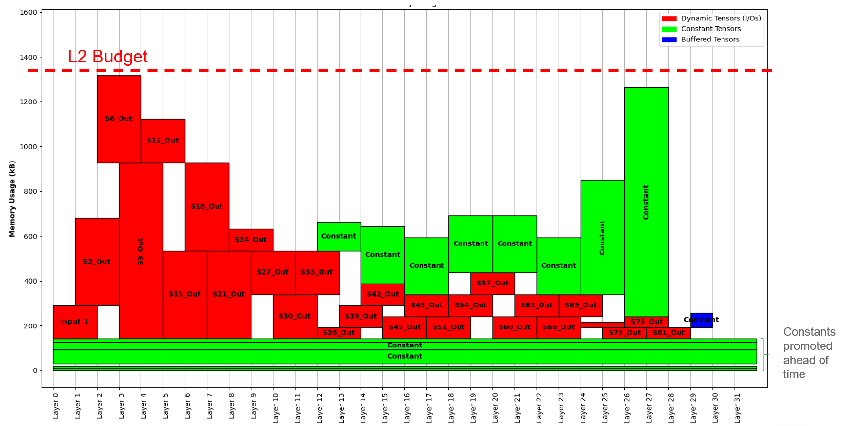
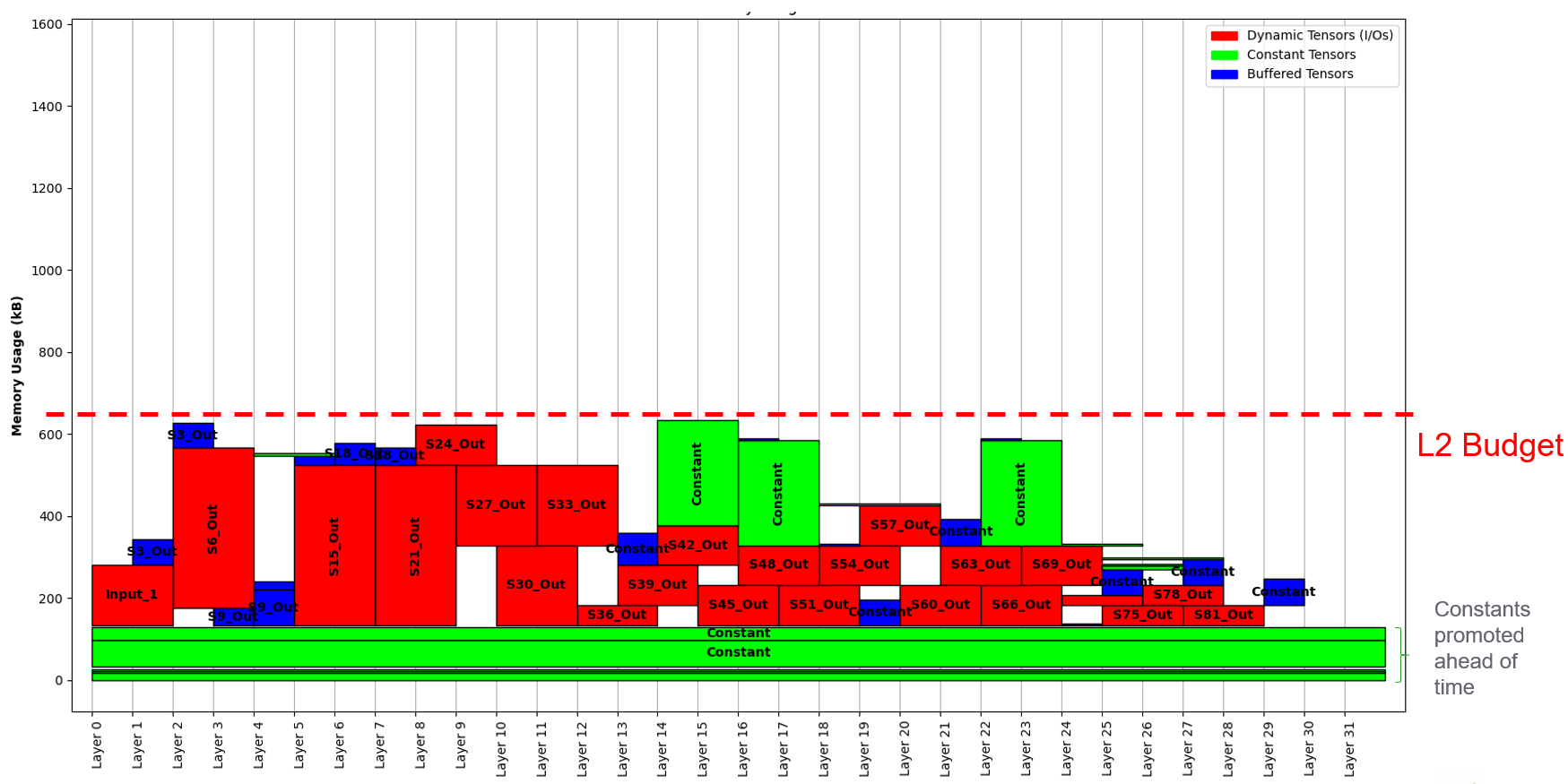
Reducing the given memory budget will exploit differend solutions with more buffered (L3 -> L2) tensors.
AT Graph Control code
Autotiler model has few APIs to control the code generation file names and includes, the memories used and the code generation options.
To set the include that are added at beggining of the generated files you can use SetUsedFilesNames API.
void SetUsedFilesNames(
    char *StdTypedefsName,          /**< File names where standard typedefs used by basic kernels are declared */
    unsigned int LibKernelFileCount,    /**< Number of header files for basic kernels to be imported into the current model, list of strings follows  */
    ...
    );
To set the name of generated code and header file the SetGeneratedFilesNames API provides two arguments.
void SetGeneratedFilesNames(
    char *CallTemplatesName,        /**< A .c file for user kernels C generated code */
    char *CallTemplatesNameHeader       /**< A .h file to export user kernels C generated code */
    );
The memory devices used by Autotiler to stock constants and dynamic buffers can be set with the SetMemoryDeviceInfos.
void SetMemoryDeviceInfos(
    int Count,      /**< Number of Items */
    ...         /* Item list */
    );
The item list is a list of Count (first argument) items where each item is a tuple of 5 elements:
AT_MemLocation_Twhich memory device (see list below) you want to configureAvailableMemory
intavailable memory to be used on this deviceMemmoryBaseName
char *a legal C var name to be used as a base in this memory deviceConstFileName
char *a file name to be used if loading constant in this device is needed, flash device onlyExtManaged
int0 if device configuration code should be generated and used internally by Autotiler, != 0 if managed externally, in this case the user should take care of properly init, configure and allocate the memory Device
The list of possible memory device to configure is the following:
AT_MEM_L3_HRAM         - L3 Hyper Ram
AT_MEM_L3_QSPIRAM      - L3 QuadSPI Ram
AT_MEM_L3_OSPIRAM      - L3 OctoSPI Ram
AT_MEM_L3_DEFAULTRAM   - L3 Default Ram. In the newest SDK the RAM available is set by the BSP thus the API hides the burdon of selecting which kind of ram you are using
AT_MEM_L3_HFLASH       - L3 Hyper Flash
AT_MEM_L3_QSPIFLASH    - L3 QuadSPI Flash
AT_MEM_L3_OSPIFLASH    - L3 OctoSPI Flash
AT_MEM_L3_MRAMFLASH    - L3 MRAM Flash
AT_MEM_L3_PRI1         - L3 Flash of first priority (used with VFS when you want more levels of flash storage, e.g. when using privileged flash)
AT_MEM_L3_PRI2         - L3 Flash of second priority (used with VFS when you want more levels of flash storage, e.g. when using privileged flash)
AT_MEM_L3_DEFAULTFLASH - L3 Default Flash. In the newest SDK the Flash available is set by the BSP thus the API hides the burdon of selecting which kind of flash you are using
AT_MEM_L2              - L2 Fabric Controller memory
AT_MEM_L1              - L1 Cluster Memory
Through SetMemoryDeviceInfos it is also possible to specify 2 flash devices for the storage of constant tensors. The second one will play the role of a Privileged Flash. This is useful in GAP9 where you have an on-chip L3 where the cost of access is much lower in terms of energy wrt external flash. The Autotiler will put as much constants as it can in the privileged flash before starting filling the external flash. This is a postprocessing action done after the whole Autotiler’s tensor allocation and starts from the non-promoted tensors, i.e. the tensors that have not been moved to L2 statically hence need to be read at runtime from L3 (more costly). This feature allows the user to use at maximum the on-chip memory. For example: NN with 2.5MB of constants parameters, all the parameters cannot fit entirely the on-chip L3 MRAM memory, so the whole file system cannot be put there. What will happen is that the tensors are split into 2 file systems, one for the internal on-chip MRAM (2MB) and the rest on the external flash. If some of those constant tensor are promoted statically in L2 at construct time, the usage of the external flash is further reduced.
There are then several code generation options that can be set with the AT_SetGraphCtrl API.
void AT_SetGraphCtrl(
    AT_GraphCtrl_T Ctrl,    /**< Which option */
    void *Val               /**< Value for this option. Use APT_OPT_ON, AT_OPT_OFF, AT_OPT_VAL(Val) */
    );
The list of all options that can be set is the following:
AT_KERNEL_BUFFER_PROMOTE             - When all user kernel arguments can fit into given L1 memory promote them to buffer, default is 1
AT_KERNEL_PARTIAL_BUFFER_PROMOTE     - When all tile of a user kernel argument across Input Features can fit into given L1 memory promote them to partial buffer, default is 1
AT_KERNEL_NOSOLUTION_ERROR           - Report an error when no tiling solution is found, default is 1
AT_GRAPH_MONITOR_CYCLES              - Enable automatic cycle capture for each node of the graph, default is 0
AT_GRAPH_MONITOR_CVAR_NAME           - When monitor cycles is on name of the C var array to receive results, default is AT_GraphPerf
AT_GRAPH_PRODUCE_NODE_NAMES          - Enable production of an array containing the name of each graph node, default is 0
AT_GRAPH_PRODUCE_NODE_CVAR_NAME      - When producing node names is on name of the C array receiving the names as strings, default is AT_GraphNodeNames
AT_GRAPH_PRODUCE_OPERINFOS           - Enable production of number of macs for each layer, default is 0
AT_GRAPH_PRODUCE_OPERINFOS_CVAR_NAME - When Number of oper Infos is on name of the C array receiving mac infos for each node, default is AT_GraphOperInfosNames
AT_GRAPH_REORDER_CONSTANT_IN         - Enable reodering of constant inputs in order to transform 2D accesses into 1D accesses, default is 1
AT_GRAPH_TRACE_EXEC                  - Enable trace of activity, default is 1
AT_GRAPH_NOINLINE_NODE               - If 1 all user kernel function is marked as noinline, default is 0
AT_GRAPH_PREF_L3_EXEC                - In case a symbol must be allocated in L3 for execution this is the prefered memory, default is AT_MEM_L3_HRAM
AT_GRAPH_CONST_EXEC_FROM_FLASH       - If 1, for constant symbol executes from home location, default is 0
AT_GRAPH_PREF_L3_HOME                - For constant symbols which L3 flash prefered memory, default is AT_MEM_L3_HFLASH
AT_GRAPH_PRIVILEGED_L3_HOME          - For constant symbols only, if they can fit a smaller but faster L3 flash put them here (Default: 0 - not used)
AT_GRAPH_DUMP_TENSOR                 - Trace selected tensors arguments at inference time, either all nodes or selected node
AT_GRAPH_DUMP_TENSOR_TO_FILE         - Dump tensors to file rather than using printfs (if AT_GRAPH_DUMP_TENSOR is set)
AT_GRAPH_DUMP_ONE_NODE               - Trace one specific graph node
AT_GRAPH_ARG2STRUCT                  - Kernel C arguments are promoted to struct
AT_GRAPH_SIZE_OPT                    - Graph constructor, runner and destructor are compiled with -Os
AT_GRAPH_WARM_CONSTRUCT              - If Warm arg should be added to constructor to bypass all but L1 mem allocation
AT_GRAPH_CHECKSUM                    - Trace checksum output tensors at inference time
AT_GRAPH_GROUP_WEIGHTS               - Group const inputs of a user kernel when they have identical structure
AT_GRAPH_ASYNC_FORK                  - Replace sync fork by async one when feasible (inner call and a single call)
AT_GRAPH_DUMP_GRAPH_OUTPUTS          - Trace graph output tensors at inference time
AT_GRAPH_RUNNER_RE_ENTRANT           - Generate re-entrant graph runner
AT_GRAPH_L1_PROMOTION                - Performs whole tensor promotion to L1 at graph level
AT_GRAPH_DISABLE_CONST_L2_PROMOTION  - Disable the Constants promotion from L3 to L2
AT_GRAPH_USE_MERGED_DMA              - Use DMA Merged copies when possible
AT_GRAPH_L2_STATIC_MEMORY_BUDGET     - L2 budget for constant promotion in L2
AT_GRAPH_L3_STATIC_MEMORY_BUDGET     - L3 budget for constant promotion in L3 RAM
Warm Constructor
The Warm contrctur permits to handle the allocation of L3, L2 and L1 static and dynamic data. There are 3 types of warm contrcutor, only L1, L1 and dynamic L2 (the L2 portion which contains only the data used during a graph execution) and all, which is L1, L2 dynamic and static and L3. The examples shown below can be found in $GAP_SDK_HOME/examples/gap9/nn/autotiler/MnistGraphWarm .
To select the warm constructor use the AT_SetGraphCtrl api with the appropriate option:
#define WARM_DISABLED  0
#define WARM_L1        1
#define WARM_L2_DYN_L1 2
#define WARM_ALL       3

AT_SetGraphCtrl(AT_GRAPH_WARM_CONSTRUCT, AT_OPT_VAL(WARM_ALL));
By default the warm constructor is disabled and the Construct/Destruct functions look like this:
int MnistCNN_Construct()
{
  AT_DEFAULTFLASH_FS_CONF_T DefaultFlashConf;

  int Error;
  AT_DEFAULTFLASH_FS_CONF_INIT(&DefaultFlashConf, AT_MEM_L3_DEFAULTFLASH, 0);
  AT_DEFAULTFLASH_FS_OPEN(&DefaultFlash, &DefaultFlashConf, "Mnist_L3_Flash_Const.dat", &Error);
  if (Error) return 1;

  Mnist_L2_Memory = (AT_L2_POINTER) AT_L2_ALLOC(0, 124692);
  if (Mnist_L2_Memory == 0) return 3;
  Mnist_L2_Memory_Dyn = (AT_L2_POINTER) AT_L2_ALLOC(0, 11264);
  if (Mnist_L2_Memory_Dyn == 0) return 3;
  Mnist_L1_Memory = (AT_L1_POINTER) AT_L1_ALLOC(0, 41632);
  if (Mnist_L1_Memory == 0) return 4;
  AT_DEFAULTFLASH_FS_FC_EVENT _UchanHF1, *UchanHF1 = &_UchanHF1;
  /* Static Moving Step1Weights, size 1600 from DefaultFlash at 122880 to (size 1600) L2 at 122880..124479 */
  AT_DEFAULTFLASH_FS_FC_COPY(&DefaultFlash, ((AT_DEFAULTFLASH_FS_EXT_ADDR_TYPE) 0 + 122880), ((AT_DEFAULTFLASH_FS_INT_ADDR_TYPE) Mnist_L2_Memory + 122880), 1600, 0, UchanHF1);
  AT_DEFAULTFLASH_FS_FC_WAIT(&DefaultFlash, UchanHF1);
  ...
  return 0;
}

int MnistCNN_Destruct()
{
  AT_L2_FREE(0, Mnist_L2_Memory, 124692);
  AT_L2_FREE(0, Mnist_L2_Memory_Dyn, 11264);
  AT_L1_FREE(0, Mnist_L1_Memory, 41632);
  AT_DEFAULTFLASH_FS_CLOSE(&DefaultFlash);
  return 0;
}
If warm is equal to 1 the generated contructor and destructor will look like this:
int MnistCNN_Construct(int Warm)
{
    if (Warm) {
        Mnist_L1_Memory = (AT_L1_POINTER) AT_L1_ALLOC(0, 41632);
        if (Mnist_L1_Memory == 0) return 4;
        return 0;
    }
    AT_DEFAULTFLASH_FS_FC_EVENT _UchanHF1, *UchanHF1 = &_UchanHF1;
    AT_DEFAULTFLASH_FS_CONF_T DefaultFlashConf;

    int Error;
    AT_DEFAULTFLASH_FS_CONF_INIT(&DefaultFlashConf, AT_MEM_L3_DEFAULTFLASH, 0);
    AT_DEFAULTFLASH_FS_OPEN(&DefaultFlash, &DefaultFlashConf, "Mnist_L3_Flash_Const.dat", &Error);
    if (Error) return 1;

    Mnist_L2_Memory = (AT_L2_POINTER) AT_L2_ALLOC(0, 135956);
    if (Mnist_L2_Memory == 0) return 3;
    Mnist_L1_Memory = (AT_L1_POINTER) AT_L1_ALLOC(0, 41632);
    if (Mnist_L1_Memory == 0) return 4;

...
}

int MnistCNN_Destruct(int Warm)
{
    if (Warm) {
        AT_L1_FREE(0, Mnist_L1_Memory, 41632);
        return 0;
    }
    AT_L2_FREE(0, Mnist_L2_Memory, 135956);
    AT_L1_FREE(0, Mnist_L1_Memory, 41632);
    AT_DEFAULTFLASH_FS_CLOSE(&DefaultFlash);
    return 0;
}
As you can see in the snippet above the Warm paramter only controls Dynamic L1 allocation, it can be 0 or >=1. If warm is equal to 1 only the L1 will be allocated in the constructor and deallocated in the destructor. A typical use case is to use the Constructor with the 0 warm parameter to initialize L2 and L3 memories and reserve the allocation (and deallocation) of L1 for later during the execution.
If Warm is equal to 2 (WARM_L2_DYN_L1) the L1 and Dynamic allocated L2 are warm. The generated contructor and destructor will look like this:
int MnistCNN_Construct(int Warm)

{
    if (Warm) {
        Mnist_L1_Memory = (AT_L1_POINTER) AT_L1_ALLOC(0, 41632);
        if (Mnist_L1_Memory == 0) return 4;
        if (Warm==2) {
            Mnist_L2_Memory_Dyn = (AT_L2_POINTER) AT_L2_ALLOC(0, 11264);
            if (Mnist_L2_Memory_Dyn == 0) return 3;
        }
        return 0;
    }
    AT_DEFAULTFLASH_FS_FC_EVENT _UchanHF1, *UchanHF1 = &_UchanHF1;
    AT_DEFAULTFLASH_FS_CONF_T DefaultFlashConf;

    int Error;
    AT_DEFAULTFLASH_FS_CONF_INIT(&DefaultFlashConf, AT_MEM_L3_DEFAULTFLASH, 0);
    AT_DEFAULTFLASH_FS_OPEN(&DefaultFlash, &DefaultFlashConf, "Mnist_L3_Flash_Const.dat", &Error);
    if (Error) return 1;

    Mnist_L2_Memory = (AT_L2_POINTER) AT_L2_ALLOC(0, 124692);
    if (Mnist_L2_Memory == 0) return 3;
    Mnist_L2_Memory_Dyn = (AT_L2_POINTER) AT_L2_ALLOC(0, 11264);
    if (Mnist_L2_Memory_Dyn == 0) return 3;
    Mnist_L1_Memory = (AT_L1_POINTER) AT_L1_ALLOC(0, 41632);
    if (Mnist_L1_Memory == 0) return 4;
    ...
}

int MnistCNN_Destruct(int Warm)

{
    if (Warm) {
        AT_L1_FREE(0, Mnist_L1_Memory, 41632);
        if (Warm==2) {
            AT_L2_FREE(0, Mnist_L2_Memory_Dyn, 11264);
        }
        return 0;
    }
    AT_L2_FREE(0, Mnist_L2_Memory, 124692);
    AT_L2_FREE(0, Mnist_L2_Memory_Dyn, 11264);
    AT_L1_FREE(0, Mnist_L1_Memory, 41632);
    AT_DEFAULTFLASH_FS_CLOSE(&DefaultFlash);
    return 0;
}
With retation to the previous one with WARM_L2_DYN_L1 you can also controll the dynamic part of the L2 allocated memory. The dynamic allocation L2 is the portion of the used L2 which is only used during Graph execution. Thus can be allocated just before the Graph execution and deallocated right after to be available for other data.
If Warm is equal to 3 (WARM_ALL) all memories are warm. The generated Constructor and Desctructor will look like:
int MnistCNN_Construct(int DoL1Alloc, int DoL2Alloc, int DoL2DynAlloc, int DoL3Init, int DoL3Alloc, int DoPromotion)

{
    if (DoL3Init) {
        AT_DEFAULTFLASH_FS_CONF_T DefaultFlashConf;

        int Error;
        AT_DEFAULTFLASH_FS_CONF_INIT(&DefaultFlashConf, AT_MEM_L3_DEFAULTFLASH, 0);
        AT_DEFAULTFLASH_FS_OPEN(&DefaultFlash, &DefaultFlashConf, "Mnist_L3_Flash_Const.dat", &Error);
        if (Error) return 1;
    }

    if (DoL2Alloc) {
        Mnist_L2_Memory = (AT_L2_POINTER) AT_L2_ALLOC(0, 124692);
        if (Mnist_L2_Memory == 0) return 3;
    }
    if (DoL2DynAlloc) {
        Mnist_L2_Memory_Dyn = (AT_L2_POINTER) AT_L2_ALLOC(0, 11264);
        if (Mnist_L2_Memory_Dyn == 0) return 3;
    }
    if (DoL1Alloc) {
        Mnist_L1_Memory = (AT_L1_POINTER) AT_L1_ALLOC(0, 41632);
        if (Mnist_L1_Memory == 0) return 4;
    }
    if (DoPromotion) {
        AT_DEFAULTFLASH_FS_FC_EVENT _UchanHF1, *UchanHF1 = &_UchanHF1;
        /* Moving Step1Weights, size 1600 from DefaultFlash at 122880 to (size 1600) L2 at 122880..124479 */
        AT_DEFAULTFLASH_FS_FC_COPY(&DefaultFlash, ((AT_DEFAULTFLASH_FS_EXT_ADDR_TYPE) 0 + 122880), ((AT_DEFAULTFLASH_FS_INT_ADDR_TYPE) Mnist_L2_Memory + 122880), 1600, 0, UchanHF1);
        AT_DEFAULTFLASH_FS_FC_WAIT(&DefaultFlash, UchanHF1);
        /* Moving Step1Biases, size 64 from DefaultFlash at 124608 to (size 64) L2 at 124608..124671 */
        AT_DEFAULTFLASH_FS_FC_COPY(&DefaultFlash, ((AT_DEFAULTFLASH_FS_EXT_ADDR_TYPE) 0 + 124608), ((AT_DEFAULTFLASH_FS_INT_ADDR_TYPE) Mnist_L2_Memory + 124608), 64, 0, UchanHF1);
        AT_DEFAULTFLASH_FS_FC_WAIT(&DefaultFlash, UchanHF1);
        /* Moving Step2Weights, size 102400 from DefaultFlash at 0 to (size 102400) L2 at 0..102399 */
        AT_DEFAULTFLASH_FS_FC_COPY(&DefaultFlash, ((AT_DEFAULTFLASH_FS_EXT_ADDR_TYPE) 0 + 0), ((AT_DEFAULTFLASH_FS_INT_ADDR_TYPE) Mnist_L2_Memory + 0), 102400, 0, UchanHF1);
        AT_DEFAULTFLASH_FS_FC_WAIT(&DefaultFlash, UchanHF1);
        /* Moving Step2Biases, size 128 from DefaultFlash at 124480 to (size 128) L2 at 124480..124607 */
        AT_DEFAULTFLASH_FS_FC_COPY(&DefaultFlash, ((AT_DEFAULTFLASH_FS_EXT_ADDR_TYPE) 0 + 124480), ((AT_DEFAULTFLASH_FS_INT_ADDR_TYPE) Mnist_L2_Memory + 124480), 128, 0, UchanHF1);
        AT_DEFAULTFLASH_FS_FC_WAIT(&DefaultFlash, UchanHF1);
        /* Moving Step3Weights, size 20480 from DefaultFlash at 102400 to (size 20480) L2 at 102400..122879 */
        AT_DEFAULTFLASH_FS_FC_COPY(&DefaultFlash, ((AT_DEFAULTFLASH_FS_EXT_ADDR_TYPE) 0 + 102400), ((AT_DEFAULTFLASH_FS_INT_ADDR_TYPE) Mnist_L2_Memory + 102400), 20480, 0, UchanHF1);
        AT_DEFAULTFLASH_FS_FC_WAIT(&DefaultFlash, UchanHF1);
        /* Moving Step3Biases, size 20 from DefaultFlash at 124672 to (size 20) L2 at 124672..124691 */
        AT_DEFAULTFLASH_FS_FC_COPY(&DefaultFlash, ((AT_DEFAULTFLASH_FS_EXT_ADDR_TYPE) 0 + 124672), ((AT_DEFAULTFLASH_FS_INT_ADDR_TYPE) Mnist_L2_Memory + 124672), 20, 0, UchanHF1);
        AT_DEFAULTFLASH_FS_FC_WAIT(&DefaultFlash, UchanHF1);
    }
    return 0;
}
int MnistCNN_Destruct(int DoL1Dealloc, int DoL2Dealloc, int DoL2DynDealloc, int DoL3Dealloc, int DoL3DeInit)

{
    if (DoL2Dealloc) {
        AT_L2_FREE(0, Mnist_L2_Memory, 124692);
    }
    if (DoL2DynDealloc) {
        AT_L2_FREE(0, Mnist_L2_Memory_Dyn, 11264);
    }
    if (DoL1Dealloc) {
        AT_L1_FREE(0, Mnist_L1_Memory, 41632);
    }
    if (DoL3DeInit) {
        AT_DEFAULTFLASH_FS_CLOSE(&DefaultFlash);
    }
    return 0;
}
As you can see L1, dynamic L2, static L2, L3 and also L3/L2 initialization (promotion) can be fully controllable from user code. Thus you need to be carefull to memory fragmentation and proper allocation of all buffer and promotion before the execution of the Graph. While in the other modes the Graph runner is always equal to the version with Warm option desactivated, with WARM_ALL you can also handle the L1. In the runner you can optionally pass a pointer to L1 if you want to handle it in your user code (this is always the case in reentrant mode, see next paragraph), otherwise you can pass NULL and will handled by the constructor / runner / destructor.
int MnistCNN(
        short int *__restrict__ Input0,
        short int *__restrict__ Output0,
        void * _L1_Memory)

{
    if (_L1_Memory) Mnist_L1_Memory = (AT_L1_POINTER) _L1_Memory;
    ...
    [Call to all nodes]
    ...
    if (_L1_Memory) Mnist_L1_Memory = 0;
    return 0;
}
Reentrant (preemptible) Graph Executor
The Autotiler model described above can be run in this mode to generate code which can be preemptible: the NN execution can be interrupted after each layer and resumed afterwards. This is useful when the application has multiple tasks to run at different times (events) with different priorities: e.g. multiple NN case: NN1 is running when a specific events triggers, suspend NN1 and run NN2, after NN2 finished, resume NN1. NOTE: The granularity of preempriveness is the single NN layer.
To activate the Reentrant mode you need to add the flag -R when running
the Autotiler executable file like so:
./MyGenerator -R
The difference in the generated code with respect to the non-reentrant mode will not be in the single layers code (the tiling strategy will be the same) but in the glue code for them. To control the flow the user has access to the Ctxt variable via multiple functions (described below). Ctxt contains the pointers to the different memory levels and the NN layers functions. Once the execution is stopped for a more prioritize task, this struct will help the user to resume the execution.
In the following all the generated functions are described:
Graph Constructor: takes a CNN_Graph_Descr_T as input, i.e. a struct with pointers to Ram, Flash, permanent L2, permanent L3. The Constructor will allocate the L2 if not provided a pointer in the descriptor and open the file system for the constants (weights/biases) read. Then it will move the permanents constants from Flash (FS) to L2 permanent
int MnistCNN_Construct(CNN_Graph_Descr_T *Descr)

{
    AT_L2_POINTER Mnist_L2_Memory = 0;
    AT_DEFAULTFLASH_FS_T *DefaultFlash = (AT_DEFAULTFLASH_FS_T *) Descr->Flash;
    int Error;
    AT_FLASH_FILE_OPEN((AT_DEFAULTFLASH_FS_T *) Descr->Flash, 0, "Mnist_L3_Flash_Const.dat", &Error);
    if (Error) return 1;
    if (Descr->L2_Memory == 0) {
        Mnist_L2_Memory = (AT_L2_POINTER) AT_L2_ALLOC(0, 124692);
        if (Mnist_L2_Memory == 0) return 3;
        Descr->L2_Memory = (void *) Mnist_L2_Memory;
    } else Mnist_L2_Memory = (AT_L2_POINTER) Descr->L2_Memory;
    AT_DEFAULTFLASH_FS_FC_EVENT _UchanHF1, *UchanHF1 = &_UchanHF1;
    /* For every promoted constant tensor, copy from flash to L2 */
    AT_DEFAULTFLASH_FS_FC_COPY();
    AT_DEFAULTFLASH_FS_FC_WAIT();
    ...
}
Context Allocator: takes the graph descriptor plus possible pointers (can be 0s) for the memory buffers designated to the Ctxt variable, L1 buffer, L2 and L3 dynamic buffers. This functions allocates space (if not provided) for the Ctxt struct in L2 and reset its content. It also allocates the other buffers if not provided (=0) and assigns the pointers value in the content of Ctxt.
MnistCNN_Ctxt_T *MnistCNN_AllocCtxt(
    CNN_Graph_Descr_T *Descr,
    MnistCNN_Ctxt_T *_Ctxt_Memory,
    AT_L1_POINTER _L1_Memory,
    AT_L2_POINTER _L2_DynMemory,
    AT_DEFAULTRAM_POINTER _L3_DynMemory,
    int *Status)

{
    *Status = 0;
    MnistCNN_Ctxt_T *Ctxt;
    if (_Ctxt_Memory==0) {
        Ctxt = (MnistCNN_Ctxt_T *) AT_L2_ALLOC(0, sizeof(MnistCNN_Ctxt_T));
        if (Ctxt == 0) {*Status = 1; return Ctxt;}
    } else Ctxt = (MnistCNN_Ctxt_T *)_Ctxt_Memory;
    Ctxt->Mnist_L2_Memory = Descr->L2_Memory;
    Ctxt->LayerIndex = 0;
    Ctxt->Layer = AllLayers;

    Ctxt->DefaultFlash = (AT_DEFAULTFLASH_FS_T *) Descr->Flash;
    if (_L2_DynMemory==0) {
        AT_L2_POINTER Mnist_L2_Memory_Dyn;
        Mnist_L2_Memory_Dyn = (AT_L2_POINTER) AT_L2_ALLOC(0, 11264);
        if (Mnist_L2_Memory_Dyn == 0) {*Status = 3; return Ctxt;}
        Ctxt->Mnist_L2_Memory_Dyn = Mnist_L2_Memory_Dyn;
    } else Ctxt->Mnist_L2_Memory_Dyn = (AT_L2_POINTER) _L2_DynMemory;
    if (_L1_Memory==0) {
        AT_L1_POINTER Mnist_L1_Memory;
        Mnist_L1_Memory = (AT_L1_POINTER) AT_L1_ALLOC(0, 41632);
        if (Mnist_L1_Memory == 0) {*Status = 4; return Ctxt;}
        Ctxt->Mnist_L1_Memory = Mnist_L1_Memory;
    } else Ctxt->Mnist_L1_Memory = (AT_L1_POINTER) _L1_Memory;
    return Ctxt;
}
Graph Runner: executes the Graph with a given input. Differently from non-reentrant mode, here after each layer the execution is put in yield, in this way it can be interrupted by higher priority tasks. The progress of the execution is kept in Ctxt (->LayerIndex stores the last executed layer) in order to be able to resume it afterwards.
int MnistCNN(
        void *_Ctxt,
        short int *__restrict__ Input0,
        short int *__restrict__ Output0,
        void * _L1_Memory)

{
    MnistCNN_Ctxt_T *Ctxt = _Ctxt;
    if (_L1_Memory) Ctxt->Mnist_L1_Memory = (AT_L1_POINTER) _L1_Memory;
    while (Ctxt->LayerIndex<4) {
        if (Ctxt->LayerIndex==0) {
            Ctxt->Input0 = Input0;
            Ctxt->Output0 = Output0;
        }
        Ctxt->Layer[Ctxt->LayerIndex++](Ctxt);
        if (AT_YIELD()) return 0; // <-- Yield point after each layer execution
    }
    Ctxt->LayerIndex = 0;
    if (_L1_Memory) Ctxt->Mnist_L1_Memory = 0;
    return 0;
}
Graph Destructor: deallocates all the allocated permanent memories (L2 and L3) and closes the file system.
int MnistCNN_Destruct(
    CNN_Graph_Descr_T *Descr,
    int Free_L2_Memory,
    int Free_L3_Memory)

{   if (Free_L2_Memory) AT_L2_FREE(0, Descr->L2_Memory, 124692);
    AT_FLASH_FILE_CLOSE((AT_DEFAULTFLASH_FS_T *)Descr->Flash);
    return 0;
}
Context DeAllocator: optionally frees the dynamic memory buffers and the context.
void MnistCNN_DeAllocCtxt(
    MnistCNN_Ctxt_T *_Ctxt,
    int Free_Ctxt_Memory,
    int Free_L1_Memory,
    int Free_L2_DynMemory,
    int Free_L3_DynMemory)

{
    MnistCNN_Ctxt_T *Ctxt = (MnistCNN_Ctxt_T *) _Ctxt;

    if (Free_L2_DynMemory==0) AT_L2_FREE(0, Ctxt->Mnist_L2_Memory_Dyn, 11264);
    if (Free_L1_Memory==0) AT_L1_FREE(0, Ctxt->Mnist_L1_Memory, 41632);
    if (Free_Ctxt_Memory) AT_L2_FREE(0, Ctxt, sizeof(MnistCNN_Ctxt_T));
}
Context Control: takes as argument an Action: if 1, abort the execution by setting the LayerIndex to the last element, if 0 reset the execution to the first layer (LayerIndex = 0)
void MnistCNN_ControlCtxt(void *_Ctxt, int Action)

{
    MnistCNN_Ctxt_T *Ctxt = (MnistCNN_Ctxt_T *) _Ctxt;

    if (Action==0) Ctxt->LayerIndex = 0;
    else if (Action==1) Ctxt->LayerIndex = 4;
}
Graph Memory Info: function used to get the memory used by the graph. Takes as argument the memory level (Which: AT_MEM_TYPE, enum to select the memory)
int MnistCNN_Memory(AT_MEM_TYPE Which)

{
    switch (Which) {
        case AT_L1_MEM:     return 41632; /* L1 Memory */
        case AT_L2_MEM:     return 124692; /* L2 Memory, permanent */
        case AT_L2_DYN_MEM: return 11264; /* L2 Memory, dynamic */
        case AT_L3_MEM:     return 0; /* L3 Memory, permanent */
        case AT_L3_DYN_MEM: return 0; /* L3 Memory, dynamic */
        case AT_CTXT_MEM:   return sizeof(MnistCNN_Ctxt_T); /* Context Memory */
    }
    return 0;
}
- Getters and Setters for the Ctxt: the elements of the Ctxt struct can be set/get with these functions. The possible options are:
LayerIndex: last layer executed by the runner before being stopped
XXMemory Pointers: the memory pointers allocated for the NN run. Only the ones used effectively by the network will have a getter/setter.
int MnistCNN_CtxtGetLayerIndex(AT_CTXT_TYPE _Ctxt)

{
    MnistCNN_Ctxt_T *Ctxt = (MnistCNN_Ctxt_T *) _Ctxt;
    return Ctxt->LayerIndex;
}

AT_L2_POINTER MnistCNN_CtxtGetL2MemoryPointer(AT_CTXT_TYPE _Ctxt)

{
    MnistCNN_Ctxt_T *Ctxt = (MnistCNN_Ctxt_T *) _Ctxt;
    return Ctxt->Mnist_L2_Memory;

}
AT_L2_POINTER MnistCNN_CtxtGetL2MemoryDynPointer(AT_CTXT_TYPE _Ctxt)

{
    MnistCNN_Ctxt_T *Ctxt = (MnistCNN_Ctxt_T *) _Ctxt;
    return Ctxt->Mnist_L2_Memory_Dyn;

}
AT_L1_POINTER MnistCNN_CtxtGetL1MemoryPointer(AT_CTXT_TYPE _Ctxt)

{
    MnistCNN_Ctxt_T *Ctxt = (MnistCNN_Ctxt_T *) _Ctxt;
    return Ctxt->Mnist_L1_Memory;

}
void MnistCNN_CtxtSetL2MemoryPointer(AT_CTXT_TYPE _Ctxt, AT_L2_POINTER MemPointer)

{
    MnistCNN_Ctxt_T *Ctxt = (MnistCNN_Ctxt_T *) _Ctxt;
    Ctxt->Mnist_L2_Memory = MemPointer;

}
void MnistCNN_CtxtSetL2MemoryDynPointer(AT_CTXT_TYPE _Ctxt, AT_L2_POINTER MemPointer)

{
    MnistCNN_Ctxt_T *Ctxt = (MnistCNN_Ctxt_T *) _Ctxt;
    Ctxt->Mnist_L2_Memory_Dyn = MemPointer;

}
void MnistCNN_CtxtSetL1MemoryPointer(AT_CTXT_TYPE _Ctxt, AT_L1_POINTER MemPointer)

{
    MnistCNN_Ctxt_T *Ctxt = (MnistCNN_Ctxt_T *) _Ctxt;
    Ctxt->Mnist_L1_Memory = MemPointer;

}
AT Model Generators Calls
Warning
This section will be soon completed
AT Model Graph dependecies
Warning
This section will be soon completed
Create your own generators aka the complete auto-tiler guide
Warning
This documentation may be out-of-date.
If you want to extend the generators suite that we provide in our SDK in this paragraph we explain all the auto-tiler fundamentals.
GAP’s memory hierarchy
GAP’s memory hierarchy is made up of three levels:
- Shared level 1 memory
Internal and tightly coupled with GAP cluster, it can deliver up to 8 parallel memory accesses in a single cycle. This is by far GAP’s fastest memory and has the highest bandwidth. As it is quite costly, its size has had to be kept relatively small, 64 Kbytes in the current configuration.
- Level 2 memory
Internal memory significantly larger than level 1, but with higher access latency (approximately 6 cycles) and lower bandwidth. Its primary role is to store programs that are then fetched by the different instruction caches attached to GAP’s various cores and to store relatively large data structures. In the current version its size is 512 Kbytes.
- Level 3 memory
External and optional (in the case of RAM). It is either read only (Flash) or read/write (RAM). Read only memory is mapped onto either the quad-SPI or HyperBus interfaces. Read/write memory is mapped onto the HyperBus interface. The latency, the access time and the bandwidth is even more limited than the other 2 memory areas and importantly accesses to level 3 memory consume more energy.
There are two DMA units. The micro-DMA unit, responsible for transfers to and from peripherals into the level 2 memory and the cluster-DMA unit, which can be used to schedule unattended transfers between level 2 and level 1 memory.
From the Autotiler POV, GAP can be summarized as the image below:
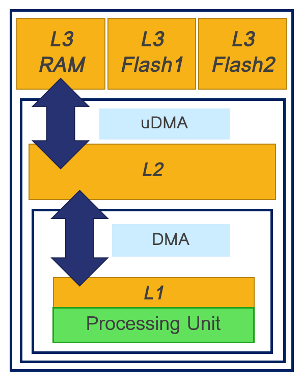
The level 1 and level 2 memories are also directly accessible by all the cores in the chip.
To keep the size of the chip as small as possible and to reduce the amount of energy spent in memory accesses GAP does not use data caching. Level 3 memory is the most constrained since data must be moved into the chip level 2 memory with the micro-DMA unit (streaming).
Auto-tiler architecture
The ideal memory model for a developer is to view memory as one large continuous area that is as big and as fast as possible. This is normally achieved by a data cache which automatically moves data between memory areas. Since GAP does not implement data caching and since GAP’s cluster is optimized for processing data in a linear or piece-wise linear fashion, we provide a software tool, the GAP auto-tiler, to help the developer by automating memory movements for programs of this type.
The auto-tiler uses defined patterns of data access to anticipate data movements ensuring that the right data is available in level 1 memory when needed. Since GAP’s cluster-DMA and micro-DMA units operate in parallel with all the GAP cores, the auto-tiler can use these units to make these pipelined memory transfers quasi-invisible from a performance point of view. The auto-tiler decomposes 1, 2, 3 and 4-dimensional data structures into a set of tiles (2-dimensional structures) and generates the C code necessary to move these tiles in and out of shared level 1 memory. The developer concentrates on the code that handles simple 2D tiles and the auto-tiler takes care of moving tiles into and out of level 1 memory as necessary and calling the developer’s code.
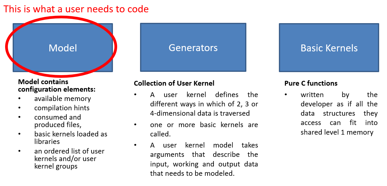
Below is a list of the entities that make up the configuration or data model necessary for the GAP auto-tiler to generate functioning code. We refer extensively to a ‘model’ which is used to indicate the use of the auto-tiler API to declare the signature of developer functions (basic kernels) and define iterated assemblies of basic kernels which actually cause the auto-tiler to generate code.
- Basic kernels
Pure C functions, these are written by the developer as if all the data structures they access can fit into shared level 1 memory (data tiles). Basic kernels can also use arguments that are prepositioned in memory (not tiled). Basic kernel functions are modeled, their call template formally described, by basic kernel models. This allows the GAP auto-tiler to generate code that calls them. They are described in detail in the section Basic kernels.
- User kernels
User kernel models group calls to basic kernels and allow the GAP auto-tiler to generate a C function for that grouping. A user kernel defines the different, predefined ways in which of 2, 3 or 4-dimensional data is traversed, and one or more basic kernels are called. A user kernel model takes arguments that describe the input, working and output data that needs to be modeled.
User kernels consume and process data through these user kernel arguments. Kernel argument models describe argument location in the memory hierarchy (level 3, level 2 or level 1), direction (in, out, in out, pure buffer), inner dimension (width and height), dimensionality (1D, 2D, 3D, 4D). Kernel argument models include several other attributes that are used to constrain the tiles that are generated from the argument (preferred size, odd/even size, etc.) or to provide hints that control the double or triple-buffering strategy used in the generated code. Calls to basic kernels can be inserted in different places in the generated iterative code (inner loop, loop prologue, loop epilogue, etc.). The calls are bound to arguments which can either be from the kernel argument model described above, direct C arguments or immediates. User kernels are described in detail in the section User kernels.
- User kernel groups
User kernel groups are models that combines or groups several user kernels together in a given order. A C function is generated from the user kernel group whose body contains calls to the sequence of user kernels with proper argument bindings between them. User kernel groups are described in detail in the section User kernel groups.
- Model control
Model control contains configuration elements such as available memory, compilation hints, consumed and produced files, basic kernels loaded as libraries and an ordered list of user kernels and/or user kernel groups. Model control is described in the section Controlling tiled code generation.
The auto-tiler model is created through a series of calls to functions from the auto-tiler library. In addition to these calls, the developer can add whatever application specific code needed. Compiling and running the model on the build system creates a set of C source files that are then compiled and run on GAP.
The basic object on which the GAP auto-tiler works is a 2D space that we call a data plane. Each user kernel argument corresponds to a data plane and potentially each user kernel argument can have a different width and height. For example, if the kernel we want to write produces one output for each 2x2 input sub region the input argument will be a data plane of WxH in size and the output argument will be a data plane of size (W/2)x(H/2).
This basic data plane can then be extended to 3 or 4 dimensions. Extending the dimension of a data plane is simply a repletion of the 2-dimensional basic data plane.
The GAP auto-tiler splits basic data planes into tiles, the number of tiles for each user kernel argument is identical but their dimension can vary from one argument to the other.
The GAP auto-tiler makes the following hypothesis about the user algorithm:
OutputDataPlane = Kernel(InputDataPlane1, InputDataPlane2, ...)
Which can be rewritten as:
For i in [0..NumberOfTiles-1]
  Tile(OutputDataPlane, i) =
    Kernel(Tile(InputDataPlane1, i), Tile(InputDataPlane2, i), ...)
Not all algorithms fits into this template but we believe it captures a large family of useful algorithms.
The illustrative examples below show how an entire auto-tiler model is constructed. Don’t worry if they are confusing at the start. As you read the other sections of the manual the examples should become clear.
Illustrative example 1 - Matrix addition
In this example, we want to add two integer matrices and store the result in a third matrix.
You can see the full code for the example in examples/autotiler/MatrixAdd.
The basic kernel that does the job of addition is MatSumPar. It takes arguments of pointers to two input tiles and one output tile, these three tiles are expected to have the same dimensions which are passed as W and H. It is expected that the 3 matrices fit into shared level 1 memory.
The basic kernel for this example is shown in the basic kernel section below.
We first model the template of basic kernel MatSumPar function call.
LibKernel("MatSumPar", CALL_PARALLEL,
        CArgs(5,
        TCArg("Word32 * __restrict__", "In1"),
        TCArg("Word32 * __restrict__", "In2"),
        TCArg("Word32 * __restrict__", "Out"),
        TCArg("unsigned int", "W"),
        TCArg("unsigned int", "H")
    ),
    "MatrixAdd_Arg_T"
);
And then we model a user kernel generator with no restrictions on the matrices dimensions (of course they need to fit into the level 2 memory). This describes the input and output parameters of the generated function and the way that the data is iterated.
void MatAddGenerator(char *UserKernelName, int W, int H)
During our build process the generator code is compiled and
MatAddGenerator("MatAdd", 200, 300) is called. The GAP auto-tiler
generates the following code:
void MatAdd(
  Word32 * __restrict__ In1,
  Word32 * __restrict__ In2,
  Word32 * __restrict__ Out,
  Kernel_T *Ker)

{
  /* Local variables used by this kernel */
  int DmaR_Evt1;
  int DmaR_Evt2;
  int DmaW_Evt1;
  int Iter, Last, NextLast, NextNextLast, InPlane, OutPlane=0;
  int N_Ti = 0, N_TiIp = 0;
  MatrixAdd_Arg_T S_KerArg0, *KerArg0 = &S_KerArg0;

  /* Initialize KerArg, Kernel invariant arguments */
  KerArg0->W = (unsigned int) (200);
  KerArg0->H = (unsigned int) (10);
  /* ================Read First Tile================ */
  /* Initial reads in L2, O_DB or O_BUFF */
  DmaR_Evt1 =  gap8_dma_memcpy((unsigned int) In1+(0),
        (unsigned int) (L1_Memory + 0)+0, 8000, DMA_COPY_IN);
  DmaR_Evt2 =  gap8_dma_memcpy((unsigned int) In2+(0),
        (unsigned int) (L1_Memory + 16000)+0, 8000, DMA_COPY_IN);
  /* ================End Read First Tile================ */
  /* Kernel Iteration Loop on tiled inner space */
  for (Iter=0; Iter<30; Iter++) {
    /* Loop Iteration Body on tiled inner space */
    /* Elaborate Last, Next_Last, Next_Next_Last */
    Last = ((Iter+1) == 30);
    NextLast = ((Iter+2) == 30);
    NextNextLast = ((Iter+3) == 30);
    /* ================Read Next Tile================ */
    gap8_dma_wait(DmaR_Evt1);
    gap8_dma_wait(DmaR_Evt2);
    if (!Last) {
      DmaR_Evt1 =  gap8_dma_memcpy((unsigned int) In1 + ((Iter+1)*8000),
          (unsigned int) (L1_Memory + 0) + 8000*((N_Ti+1) % 2), 8000, DMA_COPY_IN);
      DmaR_Evt2 =  gap8_dma_memcpy((unsigned int) In2 + ((Iter+1)*8000),
          (unsigned int) (L1_Memory + 16000) + 8000*((N_Ti+1) % 2), 8000, DMA_COPY_IN);
    }
    /* ================End Read Next Tile================ */
    /* Call Kernel LOC_INNER_LOOP */
    KerArg0->In1 = (Word32 * __restrict__)
      ((unsigned int) (L1_Memory + 0) + 8000*(N_Ti % 2));
    KerArg0->In2 = (Word32 * __restrict__)
      ((unsigned int) (L1_Memory + 16000) + 8000*(N_Ti % 2));
    KerArg0->Out = (Word32 * __restrict__)
      ((unsigned int) (L1_Memory + 32000) + 8000*(N_Ti % 2));
    gap8_task_dispatch((1<<gap8_ncore())-1, MatrixAdd, (unsigned int) KerArg0);
    MatrixAdd(KerArg0);
    /* ================Write Tile================ */
    if (Iter) {
      gap8_dma_wait(DmaW_Evt1);
    }
    DmaW_Evt1 =  gap8_dma_memcpy((unsigned int) Out + ((Iter)*8000),
      (unsigned int) (L1_Memory + 32000) + 8000*(N_Ti % 2), 8000, DMA_COPY_OUT);
    /* ================End Write Tile================ */
    N_Ti++;
    /* End Kernel Iteration Loop on tiled inner space */
  }
  Iter=30;
  /* ================Write Last Tile================ */
  gap8_dma_wait(DmaW_Evt1);
  /* ================End Write Last Tile================ */
}
Illustrative example 2 - Searching the maximum in a 2D matrix
This user kernel also operates on a 2D integer matrix but returns the maximum
value in this matrix. Here we model a classic parallel map/reduce algorithm to
accomplish the task. We use a basic kernel, KerMatrixMax, which
operates on a tile. KerMatrixMax takes as arguments: a pointer to a
tile In, the dimensions of this tile (W and H), a
pointer to the vector Out (a buffer whose dimension is the number of
tiles) to store the max for each tile. KerMatrixMax also takes an
argument CompareWithOut, which indicates if a valid maximum is already
available in the output vector and should be compared against the maximum
calculated in the current tile.
Each basic kernel call will return the maximum in a sub section of the full
input matrix. To get the final result we have to reduce the set of sub-results
into a single result. This is our second kernel: KerMatrixMaxReduction.
As a first argument In it takes the vector of maximums produced by the
first basic kernel as well as its dimension Ntile. It produces a
pointer to a single maximum in Out (a 1 x 1 tile). It should be
executed when we are done with all the tiles so the call is inserted in the
inner space iterator prologue (see the user model below).
The 2 basic kernels are first modeled.
LibKernel("KerMatrixMax", CALL_PARALLEL,      // A parallel call
  CArgs(6,
    // A tile
    TCArg("Word32 * __restrict__", "In"),
    // A vector of maximums
    TCArg("Word32 * __restrict__", "Out"),
    TCArg("unsigned int", "W"),     // Tile width
    TCArg("unsigned int", "H"),     // Tile Height
    // Which Tile - index into Out for result
    TCArg("unsigned int", "TileIndex"),
    // Out[TileIndex] contains a Max
    TCArg("unsigned int", "CompareWithOut")
  ),
  "MatrixMax_Arg_T"
);
LibKernel("KerMatrixMaxReduction", CALL_SEQUENTIAL,   // A sequential call
  CArgs(3,
    TCArg("Word32 * __restrict__", "In"),   // A vector of Maximums
    TCArg("Word32 * __restrict__", "Out"),  // Pointer to the unique Maximum
    TCArg("unsigned int", "Ntile")    // Number of entries into In
  ),
  "MatrixMaxReduction_Arg_T"
);
Then the Matrix Max user kernel generator:
/* A user kernel generator computing the max of a 2D plain matrix of size WxH */
void MatrixMax(char *Name, unsigned int W, unsigned int H)

{
  UserKernel(Name,
    // Dimension is WxH
    KernelDimensions(1, W, H, 1),
    // 2D iteration space
    KernelIterationOrder(KER_DIM2, KER_TILE),
    // Tile horizontally
    TILE_HOR,
    // User kernel C template
    CArgs(2,
      TCArg("int * __restrict__", "In"),
      TCArg("int * __restrict__", "Out")
    ),
    // 2 calls to basic kernels
    Calls(2,
      // First KerMatrixMax in the inner iterator
      Call("KerMatrixMax", LOC_INNER_LOOP,
        Bindings(6,
          K_Arg("In", KER_ARG_TILE), K_Arg("TiledOut", KER_ARG_TILE),
          K_Arg("In", KER_ARG_TILE_W), K_Arg("In", KER_ARG_TILE_H),
          K_Arg("In", KER_ARG_TILEINDEX), Imm(0))
        ),
      // Second  KerMatrixMaxReduction after we have consumed all tiles.
      // Final result goes directly to *Out thanks to C_Arg("Out")
      Call("KerMatrixMaxReduction", LOC_INNER_LOOP_EPILOG,
        Bindings(3,
          K_Arg("TiledOut", KER_ARG), C_Arg("Out"),
          K_Arg("TiledOut", KER_ARG_NTILES))
      )
    ),
    // 2 User kernel arguments
    KerArgs(2,
      // A double buffered input taken from level 2 memory
      // bound to C user kernel In
      KerArg("In", OBJ_IN_DB, W, H,
        sizeof(int), 0, 0, 0, "In", 0),
      // A dynamic buffer declared as W=1 and height=H but H will
      // be reduced to the number of used tiles
      KerArg("TiledOut", OBJ_BUFFER_DYN,
        1, H, sizeof(int), 0, 0, 0, 0, 0)
    )
  );
}
And here is the code that is generated by the auto-tiler after a call to
MatrixMax("MatMax", 200, 300).
void MatMax(
                int * __restrict__ In,
                int * __restrict__ Out,
                Kernel_T *Ker)

{
  /* Local variables used by this kernel */
  int DmaR_Evt1;
  int Iter, Last, NextLast, NextNextLast, InPlane, OutPlane=0;
  int N_Ti = 0, N_TiIp = 0;
  MatrixMax_Arg_T S_KerArg0, *KerArg0 = &S_KerArg0;

  /* Initialize KerArg, Kernel invariant arguments */
  KerArg0->W = (unsigned int) (200);
  KerArg0->CompareWithOut = (unsigned int) (0);
  /* ================Read First Tile================ */
  /* Initial reads in L2, O_DB or O_BUFF */
  DmaR_Evt1 =  gap8_dma_memcpy((unsigned int) In+(0),
      (unsigned int) (L1_Memory + 0)+0, 24800, DMA_COPY_IN);
  /* ================End Read First Tile================ */
  /* Kernel Iteration Loop on tiled inner space */
  for (Iter=0; Iter<10; Iter++) {
    /* Loop Iteration Body on tiled inner space */
    /* Elaborate Last, Next_Last, Next_Next_Last */
    Last = ((Iter+1) == 10);
    NextLast = ((Iter+2) == 10);
    NextNextLast = ((Iter+3) == 10);
    /* ================Read Next Tile================ */
    gap8_dma_wait(DmaR_Evt1);
    if (!Last) {
      DmaR_Evt1 =  gap8_dma_memcpy(
        (unsigned int) In + ((Iter+1)*24800),
        (unsigned int) (L1_Memory + 0) + 24800*((N_Ti+1) % 2),
        NextLast?16800:24800, DMA_COPY_IN);
    }
    /* ================End Read Next Tile================ */
    /* Call Kernel LOC_INNER_LOOP */
    KerArg0->In = (Word32 * __restrict__)
      ((unsigned int) (L1_Memory + 0) + 24800*(N_Ti % 2));
    KerArg0->Out = (Word32 * __restrict__)
      ((unsigned int) (L1_Memory + 49600) + 0 + (Iter)*4);
    KerArg0->H = (unsigned int) (Last?21:31);
    KerArg0->TileIndex = (unsigned int) Iter;
    gap8_task_dispatch((1<<gap8_ncore())-1, KerMatrixMax,
      (unsigned int) KerArg0);
    KerMatrixMax(KerArg0);
    N_Ti++;
    /* End Kernel Iteration Loop on tiled inner space */
  }
  Iter=10;
  /* Call Kernel LOC_INNER_LOOP_EPILOG */
  KerMatrixMaxReduction(
    (Word32 * __restrict__)
      ((unsigned int) (L1_Memory + 49600) + 0),
    (Out),
    (unsigned int)10
  );
}
Basic kernels
Basic kernels are written assuming all their data can fit into the shared level 1 memory. Usually a kernel function will access a data chunk through a pointer argument and will be informed about the data chunk characteristics by means of dimension arguments. A basic kernel manipulates a tile: one access pointer, one width argument and one height argument (a tile can also be of dimension 1). Scalar arguments, shared level 1 preloaded arguments, arguments accessed directly in level 2 can also be used by a basic kernel.
Basic kernels can be either sequential or parallel. A sequential kernel will run on a single core (core 0 of the cluster). For example, a sequential kernel can handle the configuration of the HWCE convolutional accelerator. A parallel kernel is meant to be run on all the available cores of the cluster. When it is called it is dispatched on all the active cores. Writing an optimized kernel usually involves dealing with vectorization to get as much as performance as possible from a single core and then dealing with parallelism to use as many cores in the cluster as possible.
Basic kernels define the functions manipulated by the GAP tile generator. Their interfaces (C data type template) as well as their calling nature (parallel versus sequential) are modeled.
The functions that the basic kernel models describe are called by the auto-tiler at runtime so should be in functions in source external to the model.
The following API is used to add a basic kernel model.
void LibKernel(
  // A string. The name of the kernel
  char *KernelName,
  // CALL_SEQUENTIAL when called only by cluster's core 0
  // CALL_PARALLEL when dispatched on all available cluster cores
  KernelCallTypeT CallType,
  // List of C arguments <Type, Name> where Type and Name are strings.
  // Provided by CArgs(ArgCount, List of CArgs)
  CKernel_Arg_T **Cargs,
  // C typedef name, used when CallType is parallel since
  // in this case arguments have to be promoted to a C structure
  char *ParArgTypeName
);
Example 1 - Parallel basic kernel
In this first example we show how to write a basic kernel performing a parallel addition between two 2D integer matrices with a fixed, bias offset.
The parallel addition will look like:
typedef struct {
    Word32 * __restrict__ In1;
    Word32 * __restrict__ In2;
    Word32 * __restrict__ Out;
    Word32 Bias;
    Wordu32 W;
    Wordu32 H;
} MatrixAdd_Arg_T;

void MatrixAdd(MatrixAdd_Arg_T *Arg)

{
  Word32 * __restrict__ In1 = Arg->In1;   // First input int matrix
  Word32 * __restrict__ In2 = Arg->In2;   // Second input int matrix
  Word32 * __restrict__ Out = Arg->Out;   // output int matrix
  // Pointer to a bias to be added to each matrix element sum
  Word32 * __restrict__ Bias = Arg->Bias;
  Wordu32 W = Arg->W;       // Width of the working space
  Wordu32 H = Arg->H;       // Height of the working space
  Wordu32 CoreId = gap8_coreid();     // Who am I?
    // The size of the working space is W*H, divide it by number of cores
    // (a ChunkCell)
  Wordu32 ChunkCell = ChunkSize(W*H);
    // Given who we are this is the first chunk in the working space
    // we are interested in
  Wordu32 First = CoreId*ChunkCell;
      // Given First chunk, last chunk is either full sized or capped
      // to working space size
  Wordu32 Last  = Min(First+ChunkCell, W*H);
  int i;
  for (i=First; i<Last; i++)
          Out[i] = In1[i] + In2[i] + Bias;
  // Wait on barrier until all the cores have got to here
  rt_team_barrier();
}
And this is how the function is modeled as a basic kernel:
LibKernel("MatrixAdd", CALL_PARALLEL,
  CArgs(6,
    TCArg("Word32 * __restrict__", "In1"),
    TCArg("Word32 * __restrict__", "In2"),
    TCArg("Word32 * __restrict__", "Out"),
    TCArg("Word32", "Bias"),
    TCArg("Wordu32", "W"),
    TCArg("Wordu32", "H")
  ),
  "MatrixAdd_Arg_T"
);
Example 2 - Sequential basic kernel
The second example shows how to model a sequential function to switch on the HWCE accelerator.
In this case, this is a simple sequential call to a preexisting library
function. The C function to switch on the HWCE is in the GAP run-time
and is called HWCE_Enable().
This is the way this call is modeled.
LibKernel("HWCE_Enable", CALL_SEQUENTIAL, CArgs(0), "");
User kernels
Iteration dimension, iteration space, iteration order, tiling direction
The iteration space of a user kernel can be of dimension 1, 2, 3, or 4.
The inner level of the iteration space is assumed to be 2D (with 1D as a special case where one of the inner dimensions is set to 1). The inner level is the one that will be tiled by GAP auto-tiler. In this document we refer to this inner level as a plane, either input or output.
A 2D input has width W and height H.
A 3D input is a collection of Nip 2D structure, so it’s dimension is [Nip x W x H], where Nip stands for number of input planes.
Similarly, a 3D output is a collection of Nop 2D structures, with dimension [W x H x Nop], where Nop stands for number of output planes.
A 4D input is a collection of Nip x Nop 2D structures, with dimension [Nip x W x H x Nop]
*Note: A 2D input or output can be embedded into an iteration space whose dimension is greater than 2. In this case each 2D plane is consumed several times.*
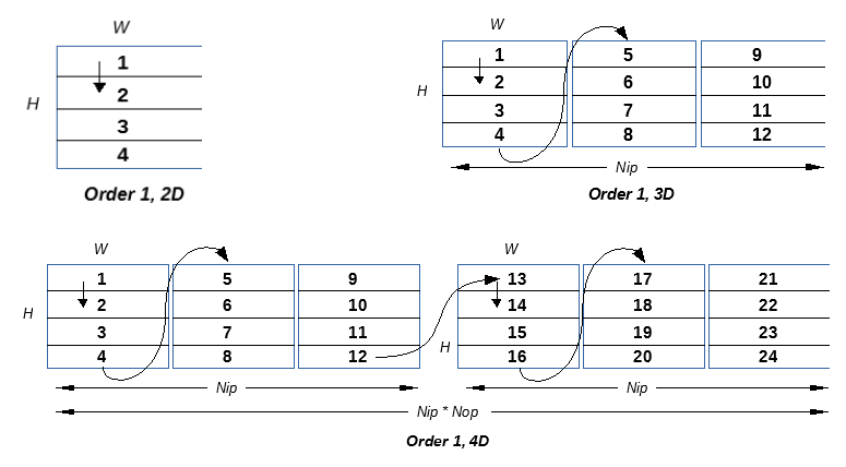
Two different iteration orders are supported when dimension is greater or equal than 3:
Order 1
for (Op=0; Op<Nop; Op++) {
    for (Ip=0; Ip<Nip; Ip++) {
        for (Tile=0; Tile<LastTile; Tile++) {
            Foo(DataTile[Ip, Tile, Op]);
        }
    }
}
The diagrams Below illustrate how tiles are traversed as a function of the dimension of the iteration space in Order 1.
Order 2
for (Op=0; Op<Nop; Op++) {
    for (Tile=0; Tile<LastTile; Tile++) {
        for (Ip=0; Ip<Nip; Ip++) {
            Foo(DataTile[Ip, Tile, Op]);
        }
    }
}
The diagrams Below illustrate how tiles are traversed as a function of the dimension of the iteration space in Order 2.
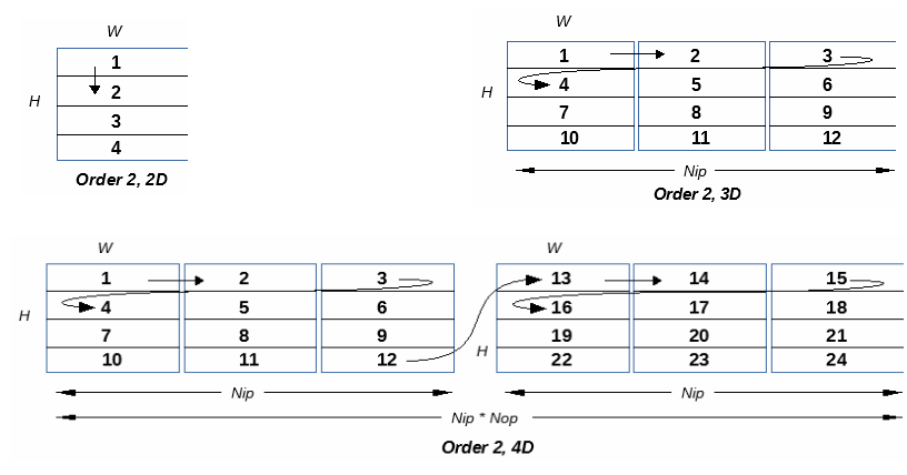
In the current implementation only order 2 is fully supported.
Tiles have 2 possible orientations:
*Horizontal:* The [W x H] data plane is divided into N tiles of size [W x h] and one last tile of size [W x hlast] where hlast < h
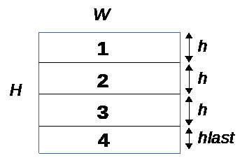
*Vertical:* The [W x H] data plane is divided into N tiles of size [w x H] and one last tile of size [wlast x H] where wlast < w
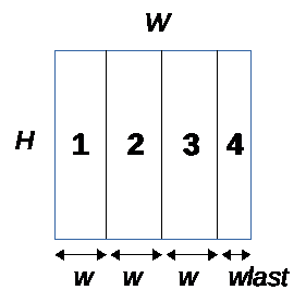
It is important to note that one of the 2 dimensions is left untouched so a single line or a single column must fit into the memory constraints given to GAP auto-tiler.
Deciding which orientation to choose is driven by the nature of the algorithm. For example, a function computing a bi-dimensional FFT on a 2D input plane of size [S x S] will execute in two passes. A first pass where a 1D FFT is applied on each line so the natural choice is horizontal. Then the second pass will apply a 1D FFT on each column of the 2D plane produced by the first pass, so vertical is the natural choice.
In the current implementation the orientation choice applies to all user kernel arguments. In future version this constraint will be removed to allow the developer to decide a different orientation for each kernel argument.
User kernel fields
A user kernel is a collection of fields. The following library function is used to create a user kernel:
Kernel_T *UserKernel(
  char *TemplateName,
  KernelDimensionT *KerDim,
  KernelIterationT *KerIter,
  Tile_Orientation_T Orientation,
  CKernel_Arg_T **CArg,
  CKernelCall_T **CCalls,
  Object_T **KerArg);
The following sections describe the content of each of the user kernel fields.
TemplateName - kernel name
A string with the kernel name which must be unique.
UserKernel("MyFavoriteKernel",
   ...
);
KerDim - kernel dimensions
Specifies the number of input planes (Nip), number of output planes
(Nop), default width (W) and height (H) of a plane
for the user kernel.
Note that Nip and Nop are shared by all kernel arguments while
W and H can be redefined for each kernel argument.
The following library function is provided to capture the user kernel dimension info:
KernelDimensionT *KernelDimensions(
  unsigned int InPlanes,
  unsigned int W,
  unsigned int H,
  unsigned int OutPlanes);
For example, MyFavoriteKernel below has 4 input planes, 4 output planes
and a default data plane of 32 column and 28 lines:
UserKernel("MyFavoriteKernel",
  KernelDimensions(4, 32, 28, 4),
  ...
);
KerIter - kernel iteration order
The iteration order captures the overall structure of the user kernel. First the number of dimensions and then the way the iteration is traversed.
Dimensions: KER_DIM2, KER_DIM3, KER_DIM4
*Iteration Order 1*
KER_DIM2, KER_TILE
: 2D. Tiled inner data plane
KER_DIM3, KER_IN_PLANE, KER_TILE
: 3D. For each
Nipin data planes all tiles in a plane,Nopis treated as equal to 1
KER_DIM3, KER_OUT_PLANE, KER_TILE
: 3D. For each
Nopout data planes all tiles in a single input plane,Nipis treated as equal to 1
KER_DIM4, KER_OUT_PLANE, KER_IN_PLANE, KER_TILE
: 4D. For each
Nopout data planes, for eachNipinput data planes, for all tile in plane
*Iteration Order 2*
KER_DIM2, KER_TILE
: 2D. Tiled inner data plane
KER_DIM3, KER_TILE, KER_IN_PLANE
: 3D. For each tile of each Nip input planes, Nop is treated as equal to 1
KER_DIM3, KER_OUT_PLANE, KER_TILE
: 3D. For each Nop out data planes all tiles in a single input plane, Nip is treated as equal to 1
KER_DIM4, KER_OUT_PLANE, KER_TILE, KER_IN_PLANE
: 4D. For each Nop out data planes, for each tile in each Nip input data planes
This is the general iteration pattern for a user kernel, then each kernel argument can traverse the whole iteration space or only a subset. For example, a 2D kernel argument when embedded in a 4D user kernel will iterate Nip*Nop times on the same WxH data plane.
Note: currently only Iteration Order 2 is fully supported.
For example, MyFavoriteKernel below follows iteration Order 2: 4 dimensions, first out-planes then tiles then in-planes:
UserKernel("MyFavoriteKernel",
  KernelDimensions(4, 32, 28, 4),
  KernelIterationOrder(KER_DIM4, KER_OUT_PLANE, KER_TILE, KER_IN_PLANE),
  ...
);
Orientation - Tiling orientation
In a 2D data plane of dimension W x H, tiling can be performed horizontally or vertically. Currently this is a user kernel level parameter and all user kernel arguments are tiled in the same direction. In the future global orientation will be able to be overridden on a per argument basis.
When a 2D data plane is tiled, all the tiles except the last one will have the same size. This size is computed to gain maximum benefit from the configured memory budget.
Orientation can be: TILE_HOR or TILE_VER.
For example MyFavoriteKernel below will tile the data plane horizontally.
UserKernel("MyFavoriteKernel",
  KernelDimensions(4, 32, 28, 4),
  KernelIterationOrder(KER_DIM4, KER_OUT_PLANE, KER_TILE, KER_IN_PLANE),
  TILE_HOR,
  ...
);
CArg - User kernel function template
A user kernel will end up as a C function after it has been processed by the auto tiler. For this reason, the C template of this function must be provided. This is like the template provided for a basic kernel, i.e. a list of C variable names and their associated C types.
The CArgs library function is used to do this. It takes two parameters.
Firstly, the number of C arguments and secondly a list of parameters modeled as
<Type Name, Arg Name> pairs, the TCArg function is used to
create the pair.
CKernel_Arg_T **CArgs(
  unsigned int ArgCount,
  ...
);

CKernel_Arg_T *TCArg(
  char *ArgType,
  char *ArgName);
For example MyFavoriteKernel below has 4 C arguments: In1,
In2, Out and Bias with their respective C types.
UserKernel("MyFavoriteKernel",
  KernelDimensions(4, 32, 28, 4),
  KernelIterationOrder(KER_DIM4, KER_OUT_PLANE, KER_TILE, KER_IN_PLANE),
  TILE_HOR,
  CArgs(4,
    TCArg("Word32 * __restrict__", "In1"),
    TCArg("Word32 * __restrict__", "In2"),
    TCArg("Word32 * __restrict__", "Out")
    TCArg("Word32 * __restrict__", "Bias")
  ),
  ...
);
You will note here that the dimension of the arguments is not passed, they will be captured in the kernel argument description part of the model if they are candidates for tiling. In case that they are pure C arguments, not candidates for tiling, then their dimensions should be passed.
CCalls - Basic kernels call sequence, call position and arguments
The CCalls field indicates the link between the User Kernel and one or more Basic Kernels. It models the sequence, call position and argument bindings for Basic Kernels called from this user kernel.
Call sequence
The location of calls to basic kernels in the user kernel iteration sequence depends on the iteration order, Order 1 or Order 2.
Here are the locations where calls can be inserted as a function of iteration order:
LOC_INNER_LOOP
LOC_INNER_LOOP_PROLOG
LOC_INNER_LOOP_EPILOG
LOC_IN_PLANE_PROLOG
LOC_IN_PLANE_EPILOG
LOC_PROLOG
LOC_EPILOG
The code fragments below show where the calls are inserted in relation to the two possible iteration orders:
*Iteration Order 1*
<LOC_PROLOG>
  for (Op=0; Op<Nop; Op++) {
    <LOC_IN_PLANE_PROLOG>
    for (Ip=0; Ip<Nip; Ip++) {
      <LOC_INNER_LOOP_PROLOG>
      for (Tile=0; Tile<LastTile; Tile++) {
        <LOC_INNER_LOOP>
        Foo(DataTile[Ip, Tile, Op]);
      }
      <LOC_INNER_LOOP_EPILOG>
    }
    <LOC_IN_PLANE_EPILOG>
  }
<LOC_EPILOG>
*Iteration Order 2*
<LOC_PROLOG>
  for (Op=0; Op<Nop; Op++) {
    <LOC_INNER_LOOP_PROLOG>
    for (Tile=0; Tile<LastTile; Tile++) {
      <LOC_INNER_PLANE_EPILOG>
      for (Ip=0; Ip<Nip; Ip++) {
        <LOC_INNER_LOOP>
        Foo(DataTile[Ip, Tile, Op]);
      }
      <LOC_INNER_PLANE_EPILOG>
    }
    <LOC_INNER_LOOP_EPILOG>
  }
<LOC_EPILOG>
Call order
At each insertion point, calls are inserted in the order they appear in the user kernel call sequence.
User kernel calls are captured by the following library call, the number of calls in the user kernel and then a list of basic kernels calls:
CKernelCall_T **Calls(
  unsigned int CallCount,
  ...
);
Each call is captured by:
CKernelCall_T *Call(
  char *CallName,
  KernelCallLocationT CallLocation,
  ArgBindingDescr_T **BindingList
);
Where CallName is a basic kernel name that must exist,
CallLocation is a call location in the iteration template and
BindingList is a list of bindings between basic kernel C formal
arguments and different entities:
ArgBindingDescr_T **Bindings(
  int BCount,
  ...
);
Call bindings
Each argument for each call can be bound to combination of user kernel arguments (tiles or attribute of tiles such as tile width and tile height), plain C arguments or immediate values.
The possible binding sources are listed below.
User kernel arguments - tile
K_Arg(UserKernelArgName, KER_ARG_TILE)
: Pointer to a tile
User kernel arguments - entire data plane
K_Arg(UserKernelArgName, KER_ARG)
: Pointer to data plane
User kernel argument attributes
Apply to tiled kernel arguments.
K_Arg(UserKernelArgName, KER_ARG_TILE_W)
: Width of the current tile. Unsigned int.
K_Arg(UserKernelArgName, KER_ARG_TILE_W0)
: Default tile width, last tile can be smaller. Unsigned int.
K_Arg(UserKernelArgName, KER_ARG_TILE_H)
: Height of the current tile. Unsigned int
K_Arg(UserKernelArgName, KER_ARG_TILE_H0)
: Default tile height, last tile can be smaller
K_Arg(UserKernelArgName, KER_ARG_NTILES)
: Number of tiles in the data plane. Unsigned int.
K_Arg(UserKernelArgName, KER_ARG_TILEINDEX)
: Current tile index. Unsigned int.
K_Arg(UserKernelArgName, KER_ARG_TILEOFFSET)
: Current tile offset starting from the origin of the iteration sub space of this user kernel argument. Unsigned int.
User kernel C arguments
C_Arg(UserKernelCArgName)
Subscripted user kernel C arguments
Subscripted by the current index of input plane, output plane or tile multiplied by a constant
C_ArgIndex(UserKernelCArgName, [Iterator], MultFactor)
: where [Iterator] is KER_IN_PLANE, KER_OUT_PLANE or KER_TILE. Note that the C kernel argument has to be a pointer for this binding to be legal
Immediate values
Imm(ImmediateIntegerValue)
Note: the binding list order has to follow the basic kernel argument list order.
For example MyFavoriteKernel below contains a single call to the
library kernel MatrixAdd located in the inner loop.
UserKernel("MyFavoriteKernel",
  KernelDimensions(4, 32, 28, 4),
  KernelIterationOrder(KER_DIM4, KER_OUT_PLANE, KER_TILE, KER_IN_PLANE),
  TILE_HOR,
  CArgs(4,
    TCArg("Word32 * __restrict__", "In1"),
    TCArg("Word32 * __restrict__", "In2"),
    TCArg("Word32 * __restrict__", "Out"),
    TCArg("Word32 * __restrict__", "Bias")
  ),
  Calls(1,
    Call("MatrixAdd", LOC_INNER_LOOP,
      Bindings(6,
        K_Arg("KerIn1", KER_ARG_TILE),    // A tile
        K_Arg("KerIn2", KER_ARG_TILE),    // A tile
        K_Arg("KerOut", KER_ARG_TILE),    // A tile
        C_ArgIndex("Bias", KER_OUT_PLANE, 1), // Bias[CurrentOutputPlane*1]
        K_Arg("KerIn1", KER_ARG_TILE_W),    // Tile width
        K_Arg("KerIn1", KER_ARG_TILE_H)   // Tile height
      )
    )
  ),
  ...
);
KerArg - User kernel arguments
User kernel arguments are the inputs and outputs to the user kernel, the entities that will undergo tiling to allow them to fit into the available level 1 memory.
A user kernel argument has a direction: input, output or input output. It can be buffered or not. Being buffered means that the entire argument content is moved into level 1 memory before the user kernel iteration space is traversed and is returned to level 2 or level 3 memory afterwards.
A user kernel argument is a collection of data planes of width W and height H. In the simplest case the data plane is a collection of 1, it is a 2D structure (Note that if you need to process 1D data you set H to 1). In more elaborate cases the kernel argument can be of dimension 3 or of dimension 4. If the direction of the argument is IN then a 3D argument is a collection of Nip WxH input data planes. Similarly, if the direction of the argument is OUT and only OUT (IN_OUT is considered as IN) then the kernel argument will be a collection of Nop W x H output data planes. A 4D argument in the current implementation can only be an input and is a collection of Nip x Nop, W x H input data planes. A user kernel argument is fully characterized by its declared width and height, its dimension and the number of input and output data planes shared by all user kernel arguments and declared in the user kernel dimension section. Note that the width and height override the default values of the kernel dimension section.
A user kernel argument has a home location in level 2 memory, the default, or in external, level 3 memory. In the case that an argument is in the external memory it can be of OUT type only if the external memory can support it. External flash only supports IN arguments while external RAM supports both IN and OUT arguments. As a special case, uninitialized buffers are transient objects with a home location in the shared level 1 memory.
A user kernel argument can be accessed in a non-pipelined way or in a pipelined way (double or triple buffered). When non-pipelined, memory transfers will affect performance since the kernel must wait for the end of the memory transfer before moving on. When pipelined, the memory transfer is performed in a different buffer than the one used for the current tile. Therefore it has all the cycles between the read and the first usage in the next iteration to complete. If the compute time spent in the basic kernels is higher than the number of cycles spent for the memory transfer, the memory transfer will not affect performance. External memory kernel arguments are always treated as pipelined object. The bandwidth gap between the external memory and the shared level 1 or the level 2 memory is such that it makes little sense to perform non-pipelined accesses to or from level 3 memory. For arguments in level 2 memory, the user can decide to let the kernel access them in a pipelined way or not.
Kernel arguments can be bound to user kernel arguments but can also be bound to an output argument of another user kernel argument belonging to the same group of user kernels (see after). They can even be working transient memory (buffer) that the kernel needs for its own sake. This buffer can be a full size data plane or only a single tile whose exact dimension will be figured out by the auto tiler.
As you can see, each user kernel argument can have a different width and height. The GAP automatic tiler models the ratios between these different dimensions and tries to find out a tile size (potentially different for each user kernel argument) that will fit within the shared level 1 memory budget it has been given. Tiles can be subject to additional constraints:
They may have to overlap. This is the case when a 2D filter is applied on a 2D data plane. Let’s assume that the set of filter coefficients is a 5 by 5 matrix then 2 adjacent tiles must overlap by 4 to be able to produce the correct output.
For algorithmic reasons it might be necessary to constrain a tile to be of odd or even size. For example, if the algorithm performs sub-sampling by a factor of 2 then all tiles but the last one must be of even dimension. Similarly, it can be desirable, for hardware constraint or performance reasons, to constrain a tile to be a multiple of a given constant. For example, on GAP the hardware convolution engine works best when it is consuming vertical strips of width 32 therefore if we set the tiling orientation to vertical and set the preferred tile size to be a multiple of 32, we will get maximum performance. As another example, if each line of a tile is given to a core for processing, then having a tile dimension being a multiple of 8 will ensure the 8 cores of the cluster are optimally balanced.
All these constraints can be expressed in a user kernel argument.
To create a kernel argument, the following library call is used:
Object_T *KerArg(
  char *KerArgName,
  Object_Type_T ObjType,
  unsigned int W,
  unsigned int H,
  unsigned int ItemSize,
  unsigned int TileOverlap,
  KernelArgConstraints_T Constraint,
  unsigned int PreferedTileSize,
  char *CArgName,
  unsigned int NextPlaneUpdate);
User kernel argument object type
A user kernel argument object type is either a flag built from a set of basic user kernel argument properties or a pre-defined name.
*Names built as a flag from user kernel argument properties*
The set of pre-defined properties which can be OR’ed (|) together is:
O_IN, O_NIN: Is an input or not an input
O_OUT, O_NOUT: Is an output or not an output
O_BUFF, O_NBUFF: Is a buffer or not a buffer
O_TILED, O_NTILED: Is tiled or not. When not tiled, the whole data plane is accessible in shared level 1 memory. For example, a 2D convolution has one argument that is tiled (the input data) and another one that is not tiled (the coefficients).
O_ONETILE, O_NONETILE: A buffer property. When ONETILE is set, a buffer of dimension WxH will be given only the dimension of a tile whose size is proportional to the size of the tiles generated for the other kernel arguments.
O_DYNTILE, O_NDYNTILE: A buffer property. When O_DYNTILE, the height if tiling orientation is horizontal or the width if orientation is vertical, of the buffer will be adjusted to the number of tile computed by GAP auto-tiler. This is useful when a dynamic buffer is needed to implement a reduction phase after a result has been computed for each tile independently and final result must be obtained combining all these results into a single one. Usually the declared W or H is the one of another user kernel input and the auto-tiler adjusts it.
O_DB, O_NDB: Argument is double or triple buffered in L1 memory, or it is not multi-buffered
O_L2DB, O_NL2DB: Argument home location is an external memory and is double or triple buffered in level 2 memory, or it is not an external memory
O_3D, O_N3D: Argument has 3 dimensions or not
- O_4D, O_N4D
: Argument has 4 dimensions or not (note that a 4D argument is also a 3D one)
For example, O_IN|O_DB|O_L2DB|O_4D is an input pipelined in level 1 memory and in level 2 memory whose home location is external memory. Its dimension is 4.
*Pre-defined names*
The diagrams below summarize the set of pre-defined names.
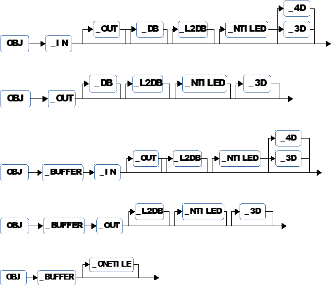
For example OBJ_IN_DB_L2DB_4D is an input pipelined in level 1 and in level 2 memory whose home location is external memory. It’s dimension is 4.
User kernel argument width and height
A pair of unsigned ints specifying the dimension of the data plane.
User kernel argument item size
An unsigned int specifying the size in bytes of the data plane elementary data type.
User kernel argument tile overlap
An unsigned int capturing the amount of overlap between two adjacent tiles. This is useful in case an output is computed as a function of a point in the input data plane and its neighborhood. If to compute an output you need inputs at a maximum distance K from the point of computation then 2 adjacent tiles should overlap by at least 2*K points.
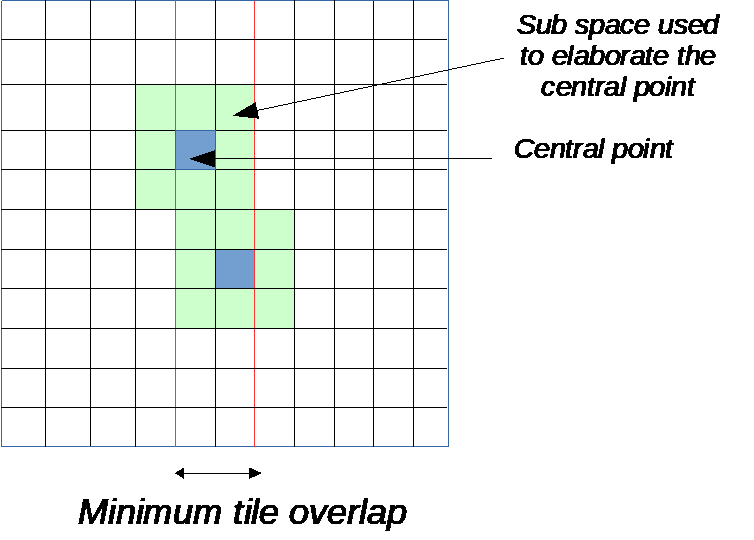
User kernel argument constraints
Specifies a constraint on a property of the tile dimension that is calculated by the GAP auto-tiler. When tiling is horizontal the constraint is on the height of the tile, and when tiling is vertical the constraint is on the width of the tile. A constraint will be applied by the auto-tiler to all the tiles except the last one. If this is not possible the model cannot be tiled.
These are the possible constraints:
typedef enum {
  OBJ_CONSTRAINTS_NONE = 0,
  OBJ_CONSTRAINTS_EVEN = (1<<1),    /* Tile variable size is even */
  OBJ_CONSTRAINTS_ODD = (1<<2),     /* Tile varaible size is odd */
  OBJ_CONSTRAINTS_ONEPREFTILE = (1<<3),   /* Limit number of used tile to just one */
  OBJ_CONSTRAINTS_TILE_HOR = (1<<4),    /* Overide default orientation to TILE_HOR */
  OBJ_CONSTRAINTS_TILE_VER = (1<<5),    /* Overide default orientation to TILE_VER */
} KernelArgConstraints_T;
User kernel argument preferred tile size
Specifies the developer’s preference for the dimension of the tile that is calculated by the GAP auto-tiler. It is expressed as an unsigned int and when not zero the preferred dimension of the tile chosen is a multiple of this value.
User kernel argument binding to C user kernel argument
Generally, a user kernel argument is connected to a C argument and in this case the name of this C argument should be provided. In the case where the user kernel argument is only internal to the user kernel or user kernel group then there is no binding and null (0) should be used.
User kernel argument next plane update
Generally, the mechanism to move from one data plane to another one in the iteration space for user kernel arguments with dimensions strictly greater than 2 is inferred from the object type. In some cases, it can be desirable to give a better control on this update process. For example, the GAP hardware convolution engine can produce 3 full 3 x 3 convolution outputs. Here 3 adjacent output data planes are involved and therefore the move to next group of outputs should use a step of 3 * size and not 1 * size of the output plane as is the case for an implicit update.
Next plane update is expressed as a non 0 unsigned integer. If 0 then default rule is applied.
Back to our simple matrix addition example, a possible final version is shown below:
UserKernel("MyFavoriteKernel",
  KernelDimensions(4, 32, 28, 4),
  KernelIterationOrder(KER_DIM4, KER_OUT_PLANE, KER_TILE, KER_IN_PLANE),
  TILE_HOR,
  CArgs(4,
  TCArg("Word32 * __restrict__", "In1"),
  TCArg("Word32 * __restrict__", "In2"),
  TCArg("Word32 * __restrict__", "Out"),
  TCArg("Word32 * __restrict__", "Bias")
  ),
  Calls(1,
    Call("MatrixAdd", LOC_INNER_LOOP,
      Bindings(6,
        K_Arg("KerIn1", KER_ARG_TILE),    // A tile
        K_Arg("KerIn2", KER_ARG_TILE),    // A tile
        K_Arg("KerOut", KER_ARG_TILE),    // A tile
        C_ArgIndex("Bias", KER_OUT_PLANE, 1), // Bias[CurrentOutputPlane*1]
        K_Arg("KerIn1", KER_ARG_TILE_W),    // Tile width
        K_Arg("KerIn1", KER_ARG_TILE_H)   // Tile height
      )
    )
  ),
  KerArgs(3,
    KerArg("KerIn1", OBJ_IN_DB_3D,     75, 75,  sizeof(Word32), 0, 0, 0, "In1", 0),
    KerArg("KerIn2", OBJ_IN_DB_3D,     75, 75,  sizeof(Word32), 0, 0, 0, "In2", 0),
    KerArg("KerOut", OBJ_OUT_DB_3D,    75, 75,  sizeof(Word32), 0, 0, 0, "Out", 0)
  )
);
The first argument is an input coming from L2 memory and it is multi buffered in shared L1 memory so that performance is optimized. The basic plane is 75 x 75 of integers (4 bytes). It has 3 dimensions and since we have declared that we have 4 input planes in the KernelDimensions section we have 4 basic planes.
The second argument has the same characteristics than the first argument.
The third argument is an output that should go to level 2 memory and that is multi buffered in level 1 memory again to incur no performance penalty due to memory transfers. It has 3 dimensions and since we have declared that we have 4 output planes in the KernelDimensions section we have 4 basic planes.
The 3 user kernel arguments are tiled.
What this example does is to add in each output matrix the sum of all input matrices plus a scalar bias.
Out[0] = (In1[0][75:75]+In2[0][75:75]+Bias[0]) +
  (In1[1][75:75]+In2[1][75:75] + Bias[0]) +
  (In1[2][75:75]+In2[2][75:75]+Bias[0]) +
  (In1[3][75:75]+In2[3][75:75] + Bias[0]);
Out[1] = (In1[0][75:75]+In2[0][75:75]+Bias[1]) +
  (In1[1][75:75]+In2[1][75:75] + Bias[1]) +
  (In1[2][75:75]+In2[2][75:75]+Bias[1]) +
  (In1[3][75:75]+In2[3][75:75] + Bias[1]);
Out[2] = (In1[0][75:75]+In2[0][75:75]+Bias[2]) +
  (In1[1][75:75]+In2[1][75:75] + Bias[2]) +
  (In1[2][75:75]+In2[2][75:75]+Bias[2]) +
  (In1[3][75:75]+In2[3][75:75] + Bias[2]);
Out[3] = (In1[0][75:75]+In2[0][75:75]+Bias[3]) +
  (In1[1][75:75]+In2[1][75:75] + Bias[3]) +
  (In1[2][75:75]+In2[2][75:75]+Bias[3]) +
  (In1[3][75:75]+In2[3][75:50] + Bias[3]);
As you can see each matrix occupies 75 * 75 * 4 = 22.5 Kbytes. There are 4 of them for In1, 4 for In2 and 4 for Out so a total of 270Kbytes. Clearly this does not fit in the shared L1 memory. The GAP auto-tiler produces code that will transparently move sections of the 270Kbytes back and forth from L2 to shared L1 and make them available to the basic kernel function doing the actual calculation (our special matrix addition) making sure all the cores are always active.
User kernel example - CNN convolution layer
We assume 3 input data planes of size W x H and 2 output data planes of size W - 4 x H - 4 (padding is not performed). The diagram below gives a high-level view of what needs to be done.
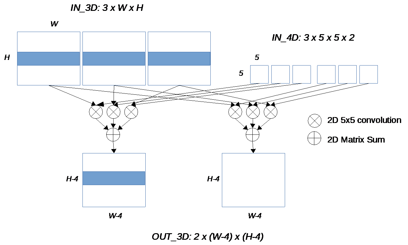
Since to get the result, we must sum up the convolution results from all input planes, we can also assume that we start the summation with a matrix made up of identical values, a bias. Planes contain fixed point numbers made up of 16 bits (short int).
Instead of having a specialized implementation, we want to allow the number of input and output data planes to be specified so we simply embed the user kernel in a C function with proper arguments.
Our 2 basic kernels are KerSetInBias that copies the same constant value in a matrix and KerDirectConv5x5_fp that takes care of the convolution itself. The convolution takes a 2D input In, a set of filter coefficients (25 in this case) and produces a 2D output. It performs normalization shifting the result by Norm.
void GenerateCnnConv5x5(char *Name, unsigned int InPlane,
  unsigned int OutPlane, unsigned int W, unsigned int H)
{
  UserKernel(Name,
    KernelDimensions(InPlane, W, H, OutPlane),
    KernelIterationOrder(KER_DIM4, KER_OUT_PLANE, KER_TILE, KER_IN_PLANE),
    TILE_HOR,
    CArgs(5,
      TCArg("short int * __restrict__", "In"),
      TCArg("short int * __restrict__", "Filter"),
      TCArg("short int * __restrict__", "Out"),
      TCArg("unsigned int",             "Norm"),
      TCArg("short int * __restrict__", "Bias")
    ),
    Calls(2,
      Call("KerSetInBias", LOC_IN_PLANE_PROLOG,
        Bindings(4,
          K_Arg("Out", KER_ARG_TILE),
          K_Arg("Out", KER_ARG_TILE_W),
          K_Arg("Out", KER_ARG_TILE_H),
          C_ArgIndex("Bias", KER_OUT_PLANE, 1)
        )
      ),
      Call("KerDirectConv5x5_fp", LOC_INNER_LOOP,
        Bindings(6,
          K_Arg("In", KER_ARG_TILE),
          K_Arg("In", KER_ARG_TILE_W),
          K_Arg("In", KER_ARG_TILE_H),
          K_Arg("Filter", KER_ARG_TILE),
          K_Arg("Out", KER_ARG_TILE),
          C_Arg("Norm")
        )
      )
    ),
    KerArgs(3,
      KerArg("In", OBJ_IN_DB_3D, W, H, sizeof(short int), 5-1, 0, 0, "In", 0),
      KerArg("Filter", OBJ_IN_DB_NTILED_4D, 5, 5,
        sizeof(short int), 0, 0, 0, "Filter", 0),
      KerArg("Out", OBJ_OUT_DB_3D, W-5+1, H-5+1,
        sizeof(short int), 0, 0, 0, "Out", 0)
    )
  );
}
This example illustrates:
3D and 4D user kernel arguments
Multi-buffered in and out
Overlapping tiles (first argument)
Untiled arguments (second argument). We need this because the filter applies to the entire input data plane not to a given point in it
Calling several basic kernels at different steps in the iteration. Setting the bias must be performed before we start producing the series of convolutions e.g before we start traversing the input planes hence in
LOC_IN_PLANE_PROLOG. The convolution itself must be performed on every single tile so it is in the inner loop.Bindings to user kernel arguments tiles and tile attributes (
K_Arg())Bindings to user kernel C arguments either as plain scalar (
C_Arg()) or as plane indexed (C_ArgIndex()).
User kernel groups
It is useful to decompose a user kernel into a group of connected user kernels. User kernel groups allow this.
A user kernel group is described by a set of 2 anchors around a list of user kernel definitions. The first anchor marks the beginning of the user kernel group and defines its name. The second anchor closes the group. Then a second section models the C kernel template for the group and how the user kernels in the user kernel group should be connected together.
Here is the API to open and to close a kernel group:
void OpenKernelGroup(
  // The name of the group, will be the name of the C template
  // generated for this group.
  char *GroupName
);

void CloseKernelGroup();
To model a kernel group the API is:
void UserKernelGroup(
  // The same name than the one used in OpenKernelGroup
  char *GroupName,
  // A list of C argunents created with CArgs(Count, ...)
  CKernel_Arg_T **Carg,
  // A list of user kernel calls created with Calls(Count, ...)
  CKernelCall_T **Ccalls
);
As a reminder:
CKernel_Arg_T **CArgs(
  unsigned int ArgCount,
  ...  // A list of TCArg()
);

CKernel_Arg_T *TCArg(
  char *ArgType,
  char *ArgName);

CKernelCall_T **Calls(
  unsigned int CallCount,
  ... // A list of UserKernelCall()
);
Instead of Call() which is used to model a call to a basic kernel,
we use UserKernelCall(). Its interface is the same as Call()
but it has some additional restrictions.
CKernelCall_T *UserKernelCall(
  char *CallName,
  KernelCallLocationT CallLocation, // Here can only be LOC_GROUP
  ArgBindingDescr_T **BindingList   // Here only these 2 bindings
  // can be used: CArg() and Imm()
);

ArgBindingDescr_T **Bindings(
  int Bcount,
  ... // A list of bindings, CArg() and Imm() only in this context
);

ArgBindingDescr_T *C_Arg( char *ArgName);

ArgBindingDescr_T *Imm( int Value);
Some details on the user kernel group call sequence:
By construction a user kernel group is made up of a sequential call to a sequence of user kernels so all calls will be performed by the cluster master core (core 0) only.
In user kernels, the call sequence is made up of basic kernels and each call is inserted at a provided location in the iteration structure. In a user kernel group, calls are only to user kernels and since there is no iteration structure in a group, the call location is
LOC_GROUP.
User kernel group example, 2D FFT
The input is a 2D byte pixel image of dimension Dim x Dim. Dim has to be a power of 2.
We first have to expand the input image into I/Q pairs. I and Q are the imaginary and real parts of a complex number, both represented as Q15 fixed point numbers in a short int. We use the Image2Complex() basic kernel. Tiling is horizontal.
Then we compute the FFT of each line of the expanded input, all the FFTs are independent. Therefore they can be evaluated in parallel. We use either a radix 4 or radix 2 FFT decimated in frequency (inputs in natural order, output in bit reverse order).
Finally, we reorder the FFT outputs with SwapSamples_2D_Horizontal_Par.
These 3 steps can be grouped together into a single user kernel in charge of the horizontal FFTs.
Once horizontal FFTs have been computed, we have to compute a 1D FFT on each column of the horizontally transformed input, so we use vertical tiling. Since the vertical FFT is also decimated in frequency, we have to reorder the vertical FFTs output. These 2 basic kernels are grouped into a single user kernel in charge of the vertical FFTs.
void FFT2D(char *Name, unsigned int Dim, int ForceRadix2)
{
  char *KerHorizontal, *KerVertical;

  // Dim is the dimension of the FFT, First select the right 1D FFT (Radix 2
  // or 4) depending on dim
  if (__builtin_popcount(Dim) != 1)
    GenTilingError(
      "FFT2D: %s, Incorrect Dim: %d, it has to be a a power of 2", Name, Dim);
  else if ((__builtin_ctz(Dim)%2)==0) {
    /* Radix 4 FFT */
    KerHorizontal = "Radix4FFT_DIF_2D_Horizontal";
    KerVertical = "Radix4FFT_DIF_2D_Vertical";
  } else {
    /* Radix 2 FFT */
    KerHorizontal = "Radix2FFT_DIF_2D_Horizontal";
    KerVertical = "Radix2FFT_DIF_2D_Vertical";
  }
  // Here we open the kernel group
  OpenKernelGroup(Name);
  // First user kernel in the group.
  // The group input is a byte image, we have to expand it to a
  // complex representation (I and Q in Q15).
  // Then we perform a 1D FFT on each line of the expanded input
  // Finally we reorder the FFT output
  UserKernel(AppendNames(Name, "Horizontal"),
    KernelDimensions(1, Dim, Dim, 1),
    KernelIterationOrder(KER_DIM2, KER_TILE),
    TILE_HOR,
    CArgs(4,
      TCArg("Wordu8 * __restrict__", "In"),
      TCArg("v2s * __restrict__", "Out"),
      TCArg("Word16 * __restrict__", "Twiddles"),
      TCArg("Word16 * __restrict__", "SwapTable")
    ),
    Calls(3,
      Call("Image2Complex", LOC_INNER_LOOP,
        Bindings(4,
          K_Arg("In", KER_ARG_TILE),
          K_Arg("Out", KER_ARG_TILE),
          K_Arg("In", KER_ARG_TILE_W),
          K_Arg("In", KER_ARG_TILE_H))),
      Call(KerHorizontal, LOC_INNER_LOOP,
        Bindings(4,
          K_Arg("Out", KER_ARG_TILE),
          C_Arg("Twiddles"),
          K_Arg("Out", KER_ARG_TILE_W),
          K_Arg("Out", KER_ARG_TILE_H))),
      Call("SwapSamples_2D_Horizontal_Par", LOC_INNER_LOOP,
        Bindings(4,
          K_Arg("Out", KER_ARG_TILE),
          C_Arg("SwapTable"),
          K_Arg("Out", KER_ARG_TILE_W),
          K_Arg("Out", KER_ARG_TILE_H)))
    ),
    KerArgs(2,
      KerArg("In",  OBJ_IN_DB,  Dim, Dim, sizeof(Wordu8),  0, 0, 0, "In", 0),
      KerArg("Out", OBJ_OUT_DB, Dim, Dim, sizeof(Word32),  0, 0, 8, "Out", 0)
    )
  );
  // Second user kernel in the group.
  // This user kernel takes as an input the output of the horizontal FFT step
  // It performs a 1D FFT on each column of the input matrix (note that here
  // the tiling is vertical)
  // Finally we reorder the FFT output and we are done
  UserKernel(AppendNames(Name, "Vertical"),
    KernelDimensions(1, Dim, Dim, 1),
    KernelIterationOrder(KER_DIM2, KER_TILE),
    TILE_VER,
    CArgs(3,
      TCArg("Word16 * __restrict__", "InOut"),
      TCArg("Word16 * __restrict__", "Twiddles"),
      TCArg("Word16 * __restrict__", "SwapTable")
    ),
    Calls(2,
      Call(KerVertical, LOC_INNER_LOOP,
        Bindings(4,
          K_Arg("InOut", KER_ARG_TILE),
          C_Arg("Twiddles"),
          K_Arg("InOut", KER_ARG_TILE_H),
          K_Arg("InOut", KER_ARG_TILE_W))),
      Call("SwapSamples_2D_Vertical_Par", LOC_INNER_LOOP,
        Bindings(4,
          K_Arg("InOut", KER_ARG_TILE),
          C_Arg("SwapTable"),
          K_Arg("InOut", KER_ARG_TILE_H),
          K_Arg("InOut", KER_ARG_TILE_W)))
    ),
    KerArgs(1,
      KerArg("InOut", OBJ_IN_OUT_DB, Dim, Dim, sizeof(Word32), 0, 0, 8, "InOut", 0)
    )

  );
  // The kernel group is closed
  CloseKernelGroup();

  // Now we model the kernel group C template, then we provide the list of
  // user calls, in this case horizontal and vertical FFT and we model the
  // bindings between user kernel group C arguments and the 2 called
  // user kernels in the group
  UserKernelGroup(Name,
    CArgs(4,
      TCArg("Wordu8 * __restrict__", "In"),
      TCArg("Word32 * __restrict__", "Out"),
      TCArg("Word16 * __restrict__", "Twiddles"),
      TCArg("Word16 * __restrict__", "SwapTable")
    ),
    Calls(2,
      UserKernelCall(AppendNames(Name, "Horizontal"), LOC_GROUP,
        Bindings(4, C_Arg("In"), C_Arg("Out"), C_Arg("Twiddles"), C_Arg("SwapTable"))),
      UserKernelCall(AppendNames(Name, "Vertical"),   LOC_GROUP,
        Bindings(3, C_Arg("Out"), C_Arg("Twiddles"), C_Arg("SwapTable")))
    )
  );
}
Controlling tiled code generation
As already mentioned a model is just a C program. To get the generated code you need to compile and execute the model.
The model makes use of the GAP auto-tiler library calls for which a header
file needs to be included and a library to be added to the link list. All
interfaces and data types are declared in AutoTilerLib.h and the library
itself is AutoTilerLib.a.
Below is a simple example of a complete generator using the auto-tiler,
MyProgram.c:
#include <stdint.h>
#include <stdio.h>
#include "AutoTilerLib.h"

void MySetOfUserKernels(unsigned int L1_Memory_Budget)
{
  /*
    Here you include:
      Loading basic kernel libraries
      List of user kernels and user kernels groups
  */
}

void ConfigureTiler()
{
  /*
    Here you include
    header files for the basic kernels
    Files to be produced
    Tiler options
    ...
  */
}

int main(int argc, char **argv)
{
  // First use library API to parse program options and initialize the tile
  if (TilerParseOptions(argc, argv)) {
    printf("Failed to initialize or incorrect arguments.\n"); return 1;
  }
  // Setup Gap8 auto tiler preferences
  ConfigureTiler();
  // Then call the function in which the user kernel models are, we give 51200 bytes of
  // memory as a budget
  MySetOfUserKernels(51200);
  // Now that the model is built we produce code for it
  GenerateTilingCode();
  return 0;
}
To compile and use the sample:
gcc
  -o MyGenerator
  -I<path to where tiler libs h files are>
  MyModel.c
  -L<path to where the tiler lib is>AutoTilerLib.a
And run MyGenerator to have the tiled user kernels generated:
./MyGenerator
The GAP auto-tiler uses and produces files, the general scheme is illustrated below:
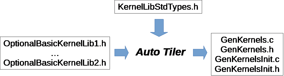
OptionalBasicKernelLibn.h: This is where the C templates for the basic kernels are expected to be found for proper compilation of the generated code. Both the C templates as well as the struct typedefs for the basic kernel arguments are included. It can be empty.
KernelLibStdTypes.h: Contains some internal tiler argument types definitions. This is the default name but it can be redefined.
The API to redefine KernelLibStdTypes.h and to provide which basic kernel libraries to use is the following:
void SetUsedFilesNames(
  /* To redefine  KernelLibStdTypes.h, if 0 uses default */
  char StdTypedefsName,
  /* Number of basic kernel libraries to be passed */
  unsigned int LibKernelFileCount,
  /* List of basic kernel libraries passed as strings */
  ...
  )
Four files are produced by the auto tiler
GenKernels.c: The generated code for all user kernels and groups in the model
GenKernels.h: Include file for the generated code
GenKernelsInit.c: Some variable definitions
GenKernelsInit.h: Include file for the initialization code
The names used here are the default names, they can be overridden using the following function:
void SetGeneratedFilesNames(
  char *ArgInitsName,    /* Redefinition of GenKernelsInit.c */
  char *ArgInitsHeaderName,   /* Redefinition of GenKernelsInit.h */
  char *CallTemplatesName,    /* Redefinition of GenKernels.c */
  char *CallTemplatesNameHeader /* Redefinition of GenKernels.h */
)
Four other symbols are also manipulated by the auto tiler:
L1_Memory: One symbol, a pointer or an array, in which all the tiles generated by the tiler will be allocated in the shared L1 memory.
L2_Memory: One symbol, a pointer or an array, in which all the tiles generated by the tiler will be allocated in the L2 memory.
AllKernels: One symbol, an array, in which user kernel descriptor is stored. Descriptors are generated only when user kernels are not inlined.
AllKernelsArgs: One symbol, an array, in which user kernel arguments descriptors are stored, AllKernels will point into it. These descriptors are generated only when user kernels are not in-lined.
These 4 names are default names, they can changed with the following function:
void SetSymbolNames(
  char *L1SymbName,
  char *L2SymbName,
  char *KernelDescrName,
  char *KernelDescArgName
)
By default these 4 symbols are managed as arrays, you can make them dynamic (pointers) in order to have the memory allocated and deallocated dynamically. The execution log of the auto tiler tells you the number of bytes to be allocated for each of them.
void SetSymbolDynamics()